Download

1 / 53
530 likes | 647 Views
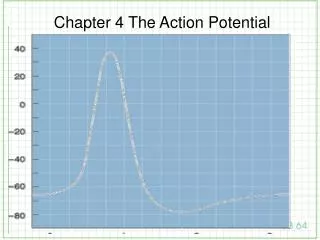
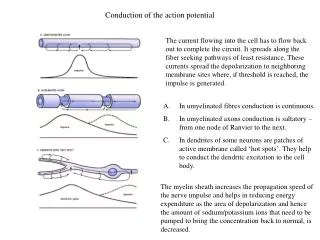
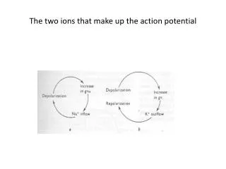
The two ions that make up the action potential. The clamp half of the voltage clamp. Axial wire electrodes used in Voltage-Clamp experiments. Hodgkin and Huxley set out to determine which ions carry the current and how the underlying membrane permeability mechanisms worked.

E N D
Hodgkin and Huxley set out to determine which ions carry the current and how the underlying membrane permeability mechanisms worked. • They reasoned that each ion seamed to move passively down their its electrochemical gradients. • Currents carried by Na+ should move inward at potentials negative to the equilibrium potential, ENa and outward for potentials positive to Ena
If the membrane is clamped at ENa, Na+ ions should make no contribution to the observed membrane current, and if the current reverses sign around ENa, it is probably carried by Na+ ions. • Similar assumptions were made for K+, Ca2+ and Cl-. • Finally, ions could be or removed from the external solution. added or removed
At resting conditions • The steady state membrane potential will be between ENa and EK, a voltage at which the inward sodium current exactly balances the outward potassium current • The total membrane current is zero ( INa + IK = 0).
If the steady state is perturbed • If pNa is increased, there will be an increase in INa . • This sodium influx causes Em to move in a positive direction from its original value. • With depolarization potassium current increases because of the difference between Em and EK.
New Steady State • The membrane will reach a new steady-state, governed by the new ratio pNa/pK . • Both INa and IK are larger than they were initially. • The two currents will again be equal to each other. • Illustrated in the next slide.
If Em Eclamp are equal there will be no current injected in to the cell. • If at time = t1 we turn on the voltage clamp and there is a sudden increase in sodium permeability. The voltage clamp will immediately detect this change, the voltage clamp amplifier will inject negative current into the axon.
In current terms • INa = gNa (Em – ENa) • or solving for gNa and rearranging: • gNa = INa/(Em – ENa) • here Em is the voltage set experimenter as the command voltage and ENa is the Nernst equilibrium potential for sodium. • Here we have talked in terms of permeability but measured in terms of conductance. They are not the same, only their time course may be the same
The voltage clamp adds and additional artificial source of current
Method for showing the sodium component by varying the sodium concentration using choline chloride for NaCl.
Another drawing showing 5 clamped voltages and their respective analog conductances
Note in the previous slide, (b) curve 2 dips deeper down than curve 1, Why?
Using specific agents to block Na+ or K+ channels in voltage clamp studies
Plotted vs. experimental derived data points • In the next slide, are conductance curves of H & H data. • The circles are data points derived from experimental results, the curve is drawn according to the equations used for calculating conductances.
Logical extension of voltage clamp experiments • A reductionist view would ask what would the current be for hydrophilic single channels. • Neher and Sakmann developed the patch-clamp
A glass pipette is pulled so that the open diameter is around 1 micron • The glass is fire-polished so there are no ragged edges. • The pipette is back filled with an ion solution; NaCl or KCl at around 3M. • When applied to the membrane, a small suction pulls the membrane into the pipette with one or more channels. This results in a resistance of over a gigasill ohms (see next slide)
General characteristics of patch-clamp data • For all patch-clamp data, abrupt transition state have been recorded. • Current flows during these open states, but no current flows in the closed states. • The preceding slide show these changes and computer idealized rendition of these changes.
Note that the gigaseal of the membrane – pipette connection is both electrically tight and machanically tight.
Ion flow through channels is fast. • It should be noted that one is observing the mechanical changes that are operating within a rather large protein complex structure. • A typical chemical enzyme assay in a test tube measure the activity of 1010 or more protein molecules. • Modern electrical devices (current to voltage converters) can measure as little as 10-13A (0.1pA) of current. • The above would not be possible unless the current flow was fast.
What the data allows one to assume about the ion channel • Typical values are 1-20 pA range. • This translate to the movement of 0.6-12 x 107 (10,000,000) ions per second through the channel. • The only metabolic turn over rate this fast can be via diffusion through a pore. • The ion channel with this fast of a rate allow the assumption that the pore must be a hydrophilic lined channels that works by diffusion.
Answers sought by patch – clamp studies • Single channel conductance: a measure of the rate which ions pass through a channel. • Ion selectivity: the nature of the ions that are allowed to p ass through a one channel. • Gating: the opening and closing of a channel unrer the influence of such factors as the transmitter - membrane voltage, the binding of neurotransmitters, hormones, and other agents to sites on the outside of the channel, and the actions of certain intracellular metabolites and enzymes. • Pharmacology: the susceptibility of the channel to various compounds that may block the pore or otherwise influence channel properties.
Single channel conductance • As in voltage clamp measure, the voltage across the membrane can be set by the investigator. • The size of the current that flows across the membrane can be plotted against voltage (see next slide). • For many channels a straight line is obtained over a wide range of voltages. • Two pieces of information are gathered; unitary conductance (b, slide below)and the reversal potential (c, slide below).
Recalling Ohms law • E = RI or E/R = • 1/R = I/V 1/R = g = ∆I/∆V Single channel conductance is in the order of picosiemens or 10-12 S. The range of measured currents todate has be from 5-400 pS.
Ion selectivity • One of the main features is the ability to test for the lack of current when the membrane is at t he equilibrium potential for that ion. • In c, two slides back the roll over from the straight line is an example. The channel may still open or close, but no current runs through the channel. • The structure of the pore is determinant as to which ion goes through the channel. • Ions, together with their associated water cloud
Ion selectivity (cont.) • Must make a tight fit with the most narrow point in the channel. • This means the channel is a selective filter. • Evolutionary pressures have designed the channels to just fit the size of neuron channels.
Gating • Ion channels a dynamic structures, they are open, open but inactivated or closed. • This is readily apparent from reading the patch clamp charts of single. • The amount of time spent in either of the two states, open/closed, will depend on the relative values of free energy. • The free energy is reflected by easily measured quantities, the rate constants for channel opening and closing
Voltage-dependent channels • When one says the gate is open or closed, we mean that the relative free energies between open and closed states have changed so that the channel is more likely to be open or closed than it was previously (b, slide below). • The next slide is representative of channel opening and closing for a potassium voltage-gated channel at different clamped voltages. • As the potential is made more positive the activation increases such that at +20 mV or higher the channel is totally activated
Voltage-gated channels (cont) • Note the time the channel spends in the open and closed state. • Further, note that the amplitude of the open state changes, which reflects the fact that the channel is sensitive to the driving state of the diffusion. • The curve is sigmoid, the steepness of which reflects the channels sensitivity to voltage. • The change in conductance at the top of the curve reflects the change in current flowing through the channel. This is called rectification and reflects that the membrane changes resistance as a function of voltage( this is not voltage-dependent gating)
The whole cell sodium current is the sum of the currents passing through all of the sodium channels in the plasma membrane. • or, • I = Npoi • where is macroscopic current, N is the number of channel, po is the probability that any channel is open and i is the current travleing through a single channel.