Download
1 / 49
490 likes | 704 Views
System Infra-Structure. By James Lum. Forward :. Infra-structure concepts in response to IBM objectives for FS (Future System) systems: 24/7 in-service operation; hardware, micro code, and software Fixes applied when system active with customer apps

E N D
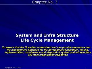
System Infra-Structure By James Lum
Forward: • Infra-structure concepts in response to IBM objectives for FS (Future System) systems: • 24/7 in-service operation; hardware, micro code, and software • Fixes applied when system active with customer apps • Full infra-structure concepts and details in: • IBM Technical Report (TR) TR 03.443 July 1992System Infra-Structure for Softwareby James LumSanta Theresa LaboratorySan Jose, CA • All the design and development was actually done in the SAK (System Assurance Kernel) testing system at IBM Poughkeepsie DSD Product Assurance, NY from 1971 thru 1979. SAK is still in use primarily for its test programs.
Overview of System Basics: • Mechanics (discussed in this presentation) • Structure • Linkage • Recovery • Serialization • Packaging • Not discussed in this presentation • Architecture, Conventions, Language, Macros • Function, Logic, Control Blocks • Documentation; Internals, User Guides • Development • Design, Coding, Testing, Releases, Maintenance
Contents: • Objectives • Overview • Structure • Call Directory • Linkage • Stacks, Module Layout • Recovery • Theory, Method, Cascading, System • Serialization • Locks, Promotion, Deadlock Recovery • Dynamic Module Replacement • Dynamic Module Loading • Boot & Load List • Overall Summary
Objectives: Define the basic structures and concepts that are valid for any programming application, especially system control programs and subsystems, that provide: • Good recovery • Design flexibility • Good performance • Ease of implementation • Ease of making changes and applying fixes • A minimal set of global rules
Method: • Combine selected solutions to basic design problems in: • Structure • Linkage • Recovery • Serialization • Development and maintenance • Flow of control • And mesh them together such that the selected solutions help solve problems in other areas in the most optimum way
Method: Continued • Thereby producing system solutions that: • Allows non-infinite recursion • Can nest interrupts (events) • Support a non-layered design • Has in-line locking for high performance serialization • Supports an imperfect lock hierarchy • Has module and system level recovery • Has no mainline code for recovery hooks • Supports multi-tasking and multi-cpus • Stresses modularity • Is easy to add system wide module call/return trace • Is easy to change and/or add new function
Structures: Call Directory (contains anchors for) Code Modules Task Stacks Data Space(s) Task Control Blocks
Structure Problems: • Logic Concerns: (What programmers do) • What are the arguments? • Where are the control blocks? • What algorithm should be used? • What other functions are needed? • Non-Logic Concerns: (What system designers do) • How is the work area acquired? • Is there enough work area space? • Where are the arguments? • What is the interface? • Can interrupts occur? • Is recursion allowed? • What is the execution state? • Can Function X be invoked?
Module A Module B Interrupt Handler Module F Structure – Task Stacks Task Code Flow • Stack is unique to task • Structured flow of control • Supports recursion • Contains work area header • Contains register save area • Contains call arguments • Contains interrupt status • PUSH/POP operations • End-of-stack handling Work Area Module A Work Area Module B Work Area Int Handler Int Status Work Area Module F
Initialization Recovery Termination Component Structure – Module Function Problems: • All code modules have four functions that are classically dispersed and written by different people: • Initialization grouped with other initialization code • Mainline code grouped with its other component code • Recovery code grouped with other recovery code • Termination grouped with other termination code How about NOT dispersing these functions?
Structure – Module Layout: Module Header Contains: Main: Name, Date, Version, Size Init: Term: Recovery Table:: • Main entry jumps to mainline code • Module name • Release Date • System/Module Version • Module Size, etc Mainline:- Function- Un-Do recovery for mainline • Pointers to: - Initialization code - Termination code Initialization:- Insert in Call Directory- Build Structures- Un-Do recovery for initialization - Recovery table Programmer Writes: Termination:- Release Structures- Un-Do recovery for termination • All code in the module • Structured programming rules • Un-do recovery • Re-entrant code • Single CSECT • Single entry point Recovery Re-Entry Point Table:
Recovery Philosophy: • When I write and deliver code, there are no bugs in it, therefore I don’t need to write recovery for my code. Besides, if I find any bugs, I fix them immediately. • But management and team leaders say that there must be recovery for my code. • The error then occurs in the code I called, not my code. All I can do is undo my changes and retry the operation once and, if unsuccessful, pass the error to whomever called me. • Recovery will be invoked if data values are incorrect or if an unexpected interrupt occurs
Recovery Methods: • In-line conditional checks:if good = ‘yes’ then call xyz(p,d,q); if returncode = ‘bad’ then good =‘no’ • Invoke a checkpoint routine • Put all retry in a separate module Is there another way?How about backing out (un-do)…and then retrying???
Recovery Objectives: • Software retry • Maintain consistent system state • No mainline code overhead • Insensitive to external changes • Insensitive to changes in inter module flow • The next three slides show some low level detail so that you get the idea of how un-do recovery works. • After that, there will be slides to show how to make the programmers job easier and ensure that the module structures are automatically generated correctly for un-do recovery.
Recovery Method Step 1 of 3 Step 1: - Write function code • Structured programming • Note downward code flow • Note call to module GET • Note serialization on lockword X Module M LK X Call GET Return; UNLK X Return;
Recovery Method Step 2 of 3 Step 1:- Write function code- Structured programming- Note downward code flow- Note call to module GET- Note serialization on lockword X Module M T: LK X A: Call GET B: Return; UNLK X C: Step 2: - Split function into major pieces • Label each major piece • Write “undo” for each major piece • Label each “undo” piece • Place “undo” pieces in opposite order Return; CC: LK X BB: Call FREE Return; AA: UNLK X
Recovery Method Step 3 of 3 Step 1:- Write function code- Structured programming- Note downward code flow- Note call to module GET- Note serialization on lockword X Module M Do 1 to 2 T: LK X A: Call GET B: Return; UNLK X C: Step 2:- Split function into major pieces- Label each major piece- Write “undo” for each major piece - Label each “undo” piece - Place “undo” pieces in opposite order Return; CC: LK X BB: Call FREE Return; AA: UNLK X END R-Return Step 3: - Put labels in recovery table • Surround all code with a DO UNTIL loop - Insert recovery return at end T: CC: A: AA: B: BB: C: CC:
Recovery Method: • Wow! That’s a lot of non-main-function work for a programmer to do! • Lets provide some macros that will generate these labels and the recovery table and the module header. • The system designer is responsible for providing these macros. • Programming language and macro preprocessor: • Allows constants address labels to be placed within and before the executable code for module header and recovery table generation. • Allows macro arguments to be collected and then expanded within the recovery redirection table.
Recovery Macros Module M M-HDR- Builds module header containing name, date, entry points, re-direction table anchor M-HDR R-DO S-L(T) S-L(xx)- Creates main-line labels LK X S-L(A) Call GET R-L(xx)- Creates undo labels S-L(B) Return; R-DO- Creates DO UNTIL statement UNLK X S-L(C) R-END- Creates End for DO UNTIL statement Return; R-L(C) LK X R-PERC- Creates Call to error percolation routine R-L(B) Call FREE Return; R-TBL- Creates recovery re-direction table using labels from S-L and R-L macros R-L(A) UNLK X R-END R-PERC R-TBL
Recovery Return Percolation: • After an unsuccessful retry, control is passed back to the calling module in a “return to” fashion: • The argument passed to the return percolation function is either: • The normal return address location in the calling module • Or the location at which an interrupt occurred • The percolation function locates the calling module’s header via the task stack for security reasons. • The module header found contains a pointer to that module’s recovery redirection table. • The recovery redirection table entries are searched for an entry range that contains the location argument. • The module’s status and registers are then loaded and control is given to the location found in the recovery table. • The module will then do “undo” operations and percolate to its caller if unsuccessful to repeat the above process.
Recovery Cascading for System Recovery Module M Module N Module O Time Call Nesting Depth Normal Call/Return flow • Note downward time flow • Note call nesting depth
Recovery Cascading for System Recovery Module M Recovery Call/Return flow Module N 1. Error occurs in Module N Module O 2. Log the error 3. Percolate to Module N 4. Undo Module N code 5. Retry Module N one time Module I ٭ Log Error 6. Error re-occurs, log and repeat undo In Module N Module P 7. Percolate to Module M 8. Undo Module M code 9. Retry Module M one time 10. Call Module N 2nd time 11. Okay if retry is successful Time 12. Permanent error if not Call Nesting Depth Note: Number of actual retries based on nesting depth of the error
Recovery Summary: • Advantages: • No mainline code for recovery hooks; labels are not executable • Insensitive to external code flow changes • Module recovery cascades into system recovery • Promotes modularity and top-down structured programming • Coding rules are the same for all modules • Disadvantages: • Possible to lose asynchronous interrupts if recovery progresses thru I/O, External, or Machine Check interrupt handlers • Experience: • Recovery involves: • Unlocking locks that were locked by the main code • Releasing resources that were acquired by the main code • Can also do recovery on recovery and undo code • Recovery must be at the end of each internal subroutine • Valid to lose a control block from a free chain • Recovery is less than 10% of a module
Serialization Objectives: • Manage resources: • In a multi-programming system (multi-tasking) • In a multi-processing system (multiple CPUs) • While enabled for interrupts • While allowing recursion • While unexpected interrupts are occurring
Serialization Observations: • There are different kinds of resources; • Storage, I/O, CPUs, Time, etc • All resources are defined by control blocks • A lockword can be assigned to each group of control blocks and lockwords can be in each control block • All resources are acquired on the behalf of a task • A CPU is NOT a task, it is a resource • If a lockword is locked, the task must wait, but how?
Serialization Methods: • Disable interrupts • Special instructions (atomic operations) • TS, CS, CSD • Spin on the lockword • Lock with the task ID or the CPU ID • Also consider: • Lock hierarchies to avoid deadlocks • “Design is not done until a lock hierarchy is defined and a lock hierarchy is not defined until design is done” • Deadlock detection or avoidance? • Exclusive locks • Shared locks
Serialization Guidelines: • All resources are acquired on the behalf of a task • A locked lockword is associated with a task via a pointer to the task’s control block. NEVER with a CPU ID! • A task can have as many lockwords locked, as needed, at the same time • Exclusive locking only … No locking for read only operations: • Control blocks are filled in before they are enqueued • Single threaded chains to ensure atomic enqueues • Free chain pointers are NOT the same control block field as the active chain pointer • In unused control blocks, the active chain pointer points to the head of the active chain to steer any search code back to the active chain
Lockword Task Control Blocks XX AA BB CC DD Serialization – Lockwords and Tasks: AA@ BB@ 0 0 XX@ CC@ Current Lockword owner 1st waiter on Lockword DD@ 2nd waiter on Lockword XX@ 3rd waiter on Lockword XX@ 0 Note:- Lockword waiter chain is within the Task control blocks- Waiting Tasks contain a pointer to the lockword they are waiting on- Tasks can lock many lockwords, one at a time, but will wait on the first lockword it finds locked by another task
Lockword Task Control Blocks XX AA BB CC DD Serialization - Process Promotion: AA@ BB@ 0 0 CC@ XX@ Task AA locks lockword XX Task BB and CC are waiters XX@ 0 Task AA is dispatched (promoted) whenever it is Task BB’s and CC’s turn to run independent of any priorities Note:- Promotion reduces lockword contention (waiter) time spans- Promotion avoids long waiter queues
Lockwords Task Control Blocks XX AA YY BB Serialization – Deadlock Detection: AA@ BB@ YY@ 0 BB@ AA@ XX@ 0 Task AA locks lockword XX and Task BB locks lockword YY Task BB attempts to lock lockword XX and becomes a waiter Task AA attempts to lock lockword YY causes a deadlock if allowed Deadlock detected as part of the Process promotion algorithm: Is lockword owner is waiting on a lockword; Task control block field If no, then queue this Task as a waiter on the lockword and return If yes, locate lockword and check if the lockword owner is this Task If yes, then a deadlock will occur if this Task becomes a waiter If no, then repeat the above steps The Lock Manager uses Process Promotion to detect/prevent deadlocks
Serialization – Deadlock Recovery: Task BB Task AA - Task AA locks XX and Task BB locks YY Time - Task BB attempts to lock XX and waits LK XX LK YY - Task AA attempts to lock YY and calls the lock manager to become a waiter LK XX LK MGR LK YY Log Err Retry - Lock manager detects deadlock and calls error logging module UNLK XX - Error is percolated back to Task AA LK XX - Task AA’s undo retry code unlocks XX - Task BB now owns XX and exits wait UNLK XX - Task AA retry attempts to lock XX and waits - Task BB unlocks XX, Task AA exits wait UNLK YY - Tasks now execute normally LK YY - Deadlock resolved as a temporary error
Serialization Summary: Deadlock conditions:- At least two Tasks- At least two lockwords locked in opposite order- Conflicting relationship in time Remove any condition to eliminate the deadlock Classic solutions: Dead wait state, terminate task, lock hierarchies But undo retry recovery can change timing relationships! Design Notes:- Task waits on only one lockword at a time- Locking is done with inline code- No infinite spin locks. Can use finite spin and then suspend- Lock manager only called to put the Task on the lockword waiter chain- Lock hierarchy only needed for performance reasons- Lockword test needed to support recursion; “locked already”- Control blocks must be filled in before being enqueued- One lockword per control block and one lockword per control block chain
Serialization Results: Imperfect lock hierarchy is acceptable Lock hierarchy can evolve naturally and is not a concern Design and implementation can occur concurrently Very good performance in non-deadlock case Code and modules can be added or changed as needed functionally Lockwords can be defined and locked as needed Experience: • We had one lockword per control block and one lockword per control block chain; we never really counted or kept track of them • Deadlock error logs showed that deadlocks only occurred in stressed forced excessively recursive situations; not normal operation • Systems seem to have a natural lock hierarchy based on code flow • We never even bothered to define a lock hierarchy
Dynamic Module Replacement Objectives: Add new functions by module without recompiling the system Apply fixes without shutting down and re-booting the system Backing out bad fixes without shutting down/re-booting the system Add or remove debug tracking aids as needed Operator (System Administrator) controlled Optionally allow system to update itself
Dynamic Module Replacement: Classic Load Module: External References Physical modularity lost Pathological relationships between modules Requires compile and link edit Only local external references resolved Difficult to uncouple a module Code and Data External References Call Directory Object Modules Only No external references; all such data is located in Call Directory Physical modularity preserved Needs only a compile Easy to uncouple a module
Dynamic Module Replacement – Module Structure: Module Header Contains: Main: Name, Date, Version, Size Init: Term: Recovery Table:: • Main entry jumps to mainline code • Module name • Release Date • System/Module Version • Module Size, etc Mainline:- Function- Un-Do recovery for mainline • Pointers to: - Initialization code - Termination code Initialization:- Insert in Call Directory- Build Structures- Un-Do recovery for initialization - Recovery table Module Characteristics: Termination:- Release Structures- Un-Do recovery for termination • No external references • Entire function encapsulated • Structured programming rules • Re-entrant code • Single CSECT • Single entry point Recovery Re-Entry Point Table:
Dynamic Module Replacement Guidelines: A module is a single encapsulated unit Physical modularity as well as logical modularity Apply fixes without shutting down and re-booting the system Single entry point modules Hardware provides pointer atomicity (four byte word) Easy to Difficult Module Replacements: • No external interface changes, internal changes only • Calls to new modules; load new modules first • Interface changes; assign unused Call Directory slot first • Data structure changes; recompile and reboot recommended
Call Directory Dynamic Module Replacement: One Module Task Stacks Task A Task B Module BB KK work space BB work space Call FF Module FF FF work space FFn work space Call WW WW work space XX work space Module KK Module FFn Call FF Call XX Task A calls Module BB Module KK calls Module FFn Module BB calls Module FF Task A continues to use Module FF Task B calls Module KK Task B continues to use Module FFn Module FFn is loaded All future calls will call Module FFn Module FFn initialization replaces Module FF’s ptr in the Call Directory Module FF space reclaimed later
Module BBn Call Directory Module BB Call PP Call HH Module HH Module PP Call DD Call QQ Module QQ Call HH Dynamic Module Replacement: New Modules Module load sequence is important so that new modules are not called before being loaded Module BB to be restructured with new modules PP and QQ Modules PP and QQ assigned unused Call Directory entries Deepest nested Module QQ loaded first. QQ sets its Call Directory ptr Module PP loaded next and sets its Call Directory ptr Module BBn is loaded last and replaces Module BB’s Call Directory ptr Module BB space reclaimed later
Module BBn Call Directory Module BB Call HHn Call HH Module QQn Module HH Module QQ Module HHn Call HHn Call DD Call HH Call DD Dynamic Module Replacement: New Interface Module load sequence is important so that the new module, HHn, is not called before being loaded Module HH’s call argument interface is changed and becomes Module HHn Module HHn is assigned an unused Call Directory entry Modules HH, BB, and QQ are recompiled. Module HHn is loaded first. Module BBn is loaded next and replaces Module BB’s Call Directory ptr Module QQn is loaded last and replaces Module QQ’s Call Directory ptr Module BB’s, QQ’s, and HH’s space is reclaimed later
Dynamic Module Replacement Summary: • Guidelines: • Operations encapsulated in one re-entrant module: • Main function, initialization, termination, and recovery • Call Directory entries are NOT reused • System administrator controls sequence and timing: • No external interface changes, internal changes only; easy • Calls to new modules or new module interface; assign unused Call Directory slots and load new modules first • Data structure changes; recompile and reboot recommended • Module Initialization just replaces its pointer in the Call Directory and does not initialize any structures. Termination NOT called. • Experience: • Interface macros used to determine module re-compiles • Concept and method easy to explain & understand • Module replacement also used to back out bad changes
Dynamic Module Loading Objectives: • Improve storage space management by loading modules as needed • Activate functions dynamically as needed: • Virtual address spaces (paging support) • Multiple CPU support (2 to N processors) • Various I/O devices • Dynamically adjust system based on existing hardware • Dynamically adjust system based on Engineering Do’s and Don’ts • Non-operator control of module loading; system/program needs
Call Directory Module Directory 0 AA Module JJ Module EE 0 BB Call EE 0 CC 0 DD 0 EE Module II Dynamic Module Loading: Operation Performance penalty only when module is called the first time The system will automatically adjust to the needs of the programs Module Directory is a one-to-one Module name map of the Call Directory Call Directory pointers initialized to point to Module Directory entries An interrupt occurs when Module JJ calls Module EE Module II verifies interrupt and loads indicated module, Module EE Module EE’s initialization is called and sets its ptr in the Call Directory Module II restores Module HH’s interrupt status and re-invokes call
System Disk Boot Program Load List Data File Call Dir AA UU CC GG SS Code Modules Mod Dir Dynamic Module Loading: Boot & Load List Data File is a compiled Call Directory with a Module Name Directory Boot Program is loaded: - Storage is scanned - Locations defined Load List is a text file containing names of main system modules Data file is loaded: - Call Directory - Module Name Directory Load List is loaded Code Modules, specified in the Load List, are loaded Each module initialization is called to set Call Directory pointers
Dynamic Module Loading Summary: • Guidelines: • No external references in modules • Operations encapsulated in one re-entrant module: • Main function, initialization, termination, and recovery • System activity determines which modules are loaded • Module initialization code checks to see if its Call Directory pointer points at an entry in the Module Directory or a code module • If a code module, then this is Module replacement. Set the module pointer in the Call Directory • If not a code module, then this is Module loading. Build structures, load other needed modules, set values in the Call Directory, and finally, set the module pointer in the Call Directory Experience: • Concept and method easy to explain & understand
Overall Summary: • Guidelines: • No external references allowed! • Each code module contains function mainline, initialization, termination, and undo recovery code • Programmer writes/fixes all code in a code module Experience: • Concepts and methods easy to explain & understand • Chief designer must own/write documentation and: • Call Directory • Module name list • Module header structure • Task Control block structure • No need for lock hierarchy allowed concurrent design and implementation along with ease of adding new functions and making performance code flow changes
Application to Other Systems: • Problem: • Invested already in existing old software • Designers & programmers used to current procedures • No desire to redo existing code • Steps: • Setup Call Directory • Remove external references from code modules • Experience: • Concepts and methods easy to explain & understand • Build times shortened • Storage requirements reduced • New functions possible due to allowing recursion