Download

1 / 119
1.24k likes | 1.46k Views
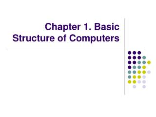
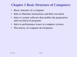
Chapter 1. Basic Structure of Computers. Functional Units. Functional Units. Arithmetic. and. Input. logic. Memory. Output. Control. I/O. Processor. Figure 1.1. Basic functional units of a computer. Information Handled by a Computer. Instructions/machine instructions

E N D
Functional Units Arithmetic and Input logic Memory Output Control I/O Processor Figure 1.1. Basic functional units of a computer.
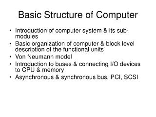
Information Handled by a Computer • Instructions/machine instructions • Govern the transfer of information within a computer as well as between the computer and its I/O devices • Specify the arithmetic and logic operations to be performed • Program • Data • Used as operands by the instructions • Source program • Encoded in binary code – 0 and 1
Memory Unit • Store programs and data • Two classes of storage • Primary storage • Fast • Programs must be stored in memory while they are being executed • Large number of semiconductor storage cells • Processed in words • Address • RAM and memory access time • Memory hierarchy – cache, main memory • Secondary storage – larger and cheaper
Arithmetic and Logic Unit (ALU) • Most computer operations are executed in ALU of the processor. • Load the operands into memory – bring them to the processor – perform operation in ALU – store the result back to memory or retain in the processor. • Registers • Fast control of ALU
Control Unit • All computer operations are controlled by the control unit. • The timing signals that govern the I/O transfers are also generated by the control unit. • Control unit is usually distributed throughout the machine instead of standing alone. • Operations of a computer: • Accept information in the form of programs and data through an input unit and store it in the memory • Fetch the information stored in the memory, under program control, into an ALU, where the information is processed • Output the processed information through an output unit • Control all activities inside the machine through a control unit
The processor : Data Path and Control • Two types of functional units: • elements that operate on data values (combinational) • elements that contain state (state elements)
Review • Activity in a computer is governed by instructions. • To perform a task, an appropriate program consisting of a list of instructions is stored in the memory. • Individual instructions are brought from the memory into the processor, which executes the specified operations. • Data to be used as operands are also stored in the memory.
A Typical Instruction • Add LOCA, R0 • Add the operand at memory location LOCA to the operand in a register R0 in the processor. • Place the sum into register R0. • The original contents of LOCA are preserved. • The original contents of R0 is overwritten. • Instruction is fetched from the memory into the processor – the operand at LOCA is fetched and added to the contents of R0 – the resulting sum is stored in register R0.
Separate Memory Access and ALU Operation • Load LOCA, R1 • Add R1, R0 • Whose contents will be overwritten?
Registers • Instruction register (IR) • Program counter (PC) • General-purpose register (R0 – Rn-1) • Memory address register (MAR) • Memory data register (MDR)
Typical Operating Steps • Programs reside in the memory through input devices • PC is set to point to the first instruction • The contents of PC are transferred to MAR • A Read signal is sent to the memory • The first instruction is read out and loaded into MDR • The contents of MDR are transferred to IR • Decode and execute the instruction
Typical Operating Steps (Cont’) • Get operands for ALU • General-purpose register • Memory (address to MAR – Read – MDR to ALU) • Perform operation in ALU • Store the result back • To general-purpose register • To memory (address to MAR, result to MDR – Write) • During the execution, PC is incremented to the next instruction
Interrupt • Normal execution of programs may be preempted if some device requires urgent servicing. • The normal execution of the current program must be interrupted – the device raises an interrupt signal. • Interrupt-service routine • Current system information backup and restore (PC, general-purpose registers, control information, specific information)
Bus Structures • There are many ways to connect different parts inside a computer together. • A group of lines that serves as a connecting path for several devices is called a bus. • Address/data/control
Bus Structure • Single-bus
Speed Issue • Different devices have different transfer/operate speed. • If the speed of bus is bounded by the slowest device connected to it, the efficiency will be very low. • How to solve this? • A common approach – use buffers.
Performance • The most important measure of a computer is how quickly it can execute programs. • Three factors affect performance: • Hardware design • Instruction set • Compiler
Performance • Processor time to execute a program depends on the hardware involved in the execution of individual machine instructions. Main Cache Processor memory memory Bus Figure 1.5. The processor cache.
Performance • The processor and a relatively small cache memory can be fabricated on a single integrated circuit chip. • Speed • Cost • Memory management
Processor Clock • Clock, clock cycle, and clock rate • The execution of each instruction is divided into several steps, each of which completes in one clock cycle. • Hertz – cycles per second
Basic Performance Equation • T – processor time required to execute a program that has been prepared in high-level language • N – number of actual machine language instructions needed to complete the execution (note: loop) • S – average number of basic steps needed to execute one machine instruction. Each step completes in one clock cycle • R – clock rate • Note: these are not independent to each other How to improve T?
Pipeline and Superscalar Operation • Instructions are not necessarily executed one after another. • The value of S doesn’t have to be the number of clock cycles to execute one instruction. • Pipelining – overlapping the execution of successive instructions. • Add R1, R2, R3 • Superscalar operation – multiple instruction pipelines are implemented in the processor. • Goal – reduce S (could become <1!)
Clock Rate • Increase clock rate • Improve the integrated-circuit (IC) technology to make the circuits faster • Reduce the amount of processing done in one basic step (however, this may increase the number of basic steps needed) • Increases in R that are entirely caused by improvements in IC technology affect all aspects of the processor’s operation equally except the time to access the main memory.
CISC and RISC • Tradeoff between N and S • A key consideration is the use of pipelining • S is close to 1 even though the number of basic steps per instruction may be considerably larger • It is much easier to implement efficient pipelining in processor with simple instruction sets • Reduced Instruction Set Computers (RISC) • Complex Instruction Set Computers (CISC)
Compiler • A compiler translates a high-level language program into a sequence of machine instructions. • To reduce N, we need a suitable machine instruction set and a compiler that makes good use of it. • Goal – reduce N×S • A compiler may not be designed for a specific processor; however, a high-quality compiler is usually designed for, and with, a specific processor.
Performance Measurement • T is difficult to compute. • Measure computer performance using benchmark programs. • System Performance Evaluation Corporation (SPEC) selects and publishes representative application programs for different application domains, together with test results for many commercially available computers. • Compile and run (no simulation) • Reference computer
Multiprocessors and Multicomputers • Multiprocessor computer • Execute a number of different application tasks in parallel • Execute subtasks of a single large task in parallel • All processors have access to all of the memory – shared-memory multiprocessor • Cost – processors, memory units, complex interconnection networks • Multicomputers • Each computer only have access to its own memory • Exchange message via a communication network – message-passing multicomputers
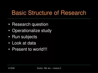
Objectives Machine instructions and program execution, including branching and subroutine call and return operations. Number representation and addition/subtraction in the 2’s-complement system. Addressing methods for accessing register and memory operands. Assembly language for representing machine instructions, data, and programs. Program-controlled Input/Output operations.
Signed Integer 3 major representations: Sign and magnitude One’s complement Two’s complement Assumptions: 4-bit machine word 16 different values can be represented Roughly half are positive, half are negative
Sign and Magnitude Representation High order bit is sign: 0 = positive (or zero), 1 = negative Three low order bits is the magnitude: 0 (000) thru 7 (111) Number range for n bits = +/-2n-1 -1 Two representations for 0
One’s Complement Representation Subtraction implemented by addition & 1's complement Still two representations of 0! This causes some problems Some complexities in addition
Two’s Complement Representation Only one representation for 0 One more negative number than positive number like 1's comp except shifted one position clockwise
Binary, Signed-Integer Representations Page 28 B V alues represented Sign and b b b b magnitude 1' s complement 2' s complement 3 2 1 0 + 7 + 7 + 7 0 1 1 1 + 6 + 6 + 6 0 1 1 0 + 5 + 5 + 5 0 1 0 1 + 4 + 4 + 4 0 1 0 0 + 3 + 3 + 3 0 0 1 1 + 2 + 2 + 2 0 0 1 0 + 1 + 1 + 1 0 0 0 1 + 0 + 0 + 0 0 0 0 0 - 0 - 7 - 8 1 0 0 0 - 1 - 6 - 7 1 0 0 1 - 2 - 5 - 6 1 0 1 0 - 3 - 4 - 5 1 0 1 1 - 4 - 3 - 4 1 1 0 0 - 5 - 2 - 3 1 1 0 1 - 6 - 1 - 2 1 1 1 0 - 7 - 0 - 1 1 1 1 1 Figure 2.1. Binary, signed-integer representations.
Addition and Subtraction – 2’s Complement 4 + 3 7 0100 0011 0111 -4 + (-3) -7 1100 1101 11001 If carry-in to the high order bit = carry-out then ignore carry if carry-in differs from carry-out then overflow 4 - 3 1 0100 1101 10001 -4 + 3 -1 1100 0011 1111 Simpler addition scheme makes twos complement the most common choice for integer number systems within digital systems
2’s-Complement Add and Subtract Operations ( + 4 ) (a) 0 0 1 0 ( + 2 ) (b) 0 1 0 0 ( ) + 0 0 1 1 + 3 + 1 0 1 0 ( - 6 ) ( - 2 ) 0 1 0 1 ( + 5 ) 1 1 1 0 ( ) + 7 (c) 1 0 1 1 ( - 5 ) (d) 0 1 1 1 + 1 1 1 0 ( - 2 ) + 1 1 0 1 ( - 3 ) 1 0 0 1 ( - 7 ) 0 1 0 0 ( + 4 ) (e) 1 1 0 1 1 1 0 1 ( - 3 ) + 1 0 0 1 0 1 1 1 - ( - 7 ) 0 1 0 0 ( + 4 ) (f) 0 0 1 0 ( + 2 ) 0 0 1 0 ( ) - 0 1 0 0 + 4 + 1 1 0 0 1 1 1 0 ( - 2 ) 0 1 1 0 0 1 1 0 (g) ( + 6 ) ( + 3 ) 0 0 1 1 1 1 0 1 - + 0 0 1 1 ( + 3 ) 1 0 0 1 (h) 1 0 0 1 ( - 7 ) 0 1 0 1 - 1 0 1 1 ( - 5 ) + 1 1 1 0 ( - 2 ) 1 0 0 1 (i) ( - 7 ) 1 0 0 1 - 0 0 0 1 ( + 1 ) + 1 1 1 1 1 0 0 0 ( - 8 ) (j) 0 0 1 0 0 0 1 0 ( + 2 ) 1 1 0 1 0 0 1 1 - + ( - 3 ) ( ) 0 1 0 1 + 5 Page 31 Figure 2.4.2's-complement Add and Subtract operations.
Overflow - Add two positive numbers to get a negative number or two negative numbers to get a positive number -1 -1 +0 +0 -2 -2 1111 0000 +1 1111 0000 +1 1110 1110 0001 0001 -3 -3 +2 +2 1101 1101 0010 0010 -4 -4 1100 +3 1100 +3 0011 0011 -5 -5 1011 1011 0100 +4 0100 +4 1010 1010 -6 -6 0101 0101 +5 +5 1001 1001 0110 0110 -7 -7 +6 +6 1000 0111 1000 0111 -8 -8 +7 +7 -7 - 2 = +7 5 + 3 = -8
Overflow Conditions 0 1 1 1 0 1 0 1 0 0 1 1 1 0 0 0 1 0 0 0 1 0 0 1 1 1 0 0 1 0 1 1 1 5 3 -8 -7 -2 7 Overflow Overflow 0 0 0 0 0 1 0 1 0 0 1 0 0 1 1 1 1 1 1 1 1 1 0 1 1 0 1 1 1 1 0 0 0 5 2 7 -3 -5 -8 No overflow No overflow Overflow when carry-in to the high-order bit does not equal carry out
Sign Extension Task: Given w-bit signed integer x Convert it to w+k-bit integer with same value Rule: Make k copies of sign bit: X = xw–1 ,…, xw–1 , xw–1 , xw–2 ,…, x0 X • • • • • • X • • • • • • w k copies of MSB w k
Sign Extension Example short int x = 15213; int ix = (int) x; short int y = -15213; int iy = (int) y;
Memory Location, Addresses, and Operation Memory consists of many millions of storage cells, each of which can store 1 bit. Data is usually accessed in n-bit groups. n is called word length. n bits first word second word • • • i th word • • • last word Figure 2.5. Memory words.