Download

1 / 50
510 likes | 645 Views
Chapter 2 Networking Standards and the OSI Model. Collected and Compiled By JD Willard MCSE, MCSA, Network+, Microsoft IT Academy Administrator Computer Information Systems Instructor Albany Technical College. Attention: Accessing Demos. This course presents many demos.

E N D
Chapter 2Networking Standards and the OSI Model Collected and Compiled By JD Willard MCSE, MCSA, Network+, Microsoft IT Academy Administrator Computer Information Systems Instructor Albany Technical College
Attention: Accessing Demos • This course presents many demos. • The Demos require that you be logged in to the Virtual Technical College web site when you click on them to run. • To access and log in to the Virtual Technical College web site: • To access the site type www.vtc.com in the url window • Log in using the username: CIS 1140 or ATCStudent1 • Enter the password: student (case sensitive) • If you should click on the demo link and you get an Access Denied it is because you have not logged in to vtc.com or you need to log out and log back in. • If you should click on the demo link and you are taken to the VTC.com web site page you should do a search in the search box for the CompTIA Network+ (2009 Objectives) Course and run the video from within that page.
Objectives • Identify organizations that set standards for networking • Describe the purpose of the OSI Model and each of its layers • Explain specific functions belonging to each OSI Model layer • Understand how two network nodes communicate through the OSI model • Discuss the structure and purpose of data packets and frames • Describe the two types of addressing covered by the OSI Model
Networking Standards Organizations • Standard • Documented agreement • Technical specifications/precise criteria • Stipulates design or performance of particular product or service • Standards important in the networking world • Wide variety of hardware and software • Ensure network design compatibility • Standards define minimum acceptable performance • Not ideal performance
Networking Standards Organizations (cont’d.) • Many different organizations oversee computer industry standards • Example: ANSI and IEEE set wireless standards • ANSI standards apply to type of NIC • IEEE standards involve communication protocols • Network professional’s responsibility • Be familiar with groups setting networking standards • Understand critical aspects of standards required by own networks
ANSI • ANSI (American National Standards Institute) • 1000+ representatives from industry and government • Determines standards for electronics industry and other fields • Requests voluntarily compliance with standards • Obtaining ANSI approval requires rigorous testing • ANSI standards documents available online • ANSI is the official U.S. representative to the International Organization for Standardization. (ISO).
EIA and TIA • EIA (Electronic Industries Alliance) • Trade organization • Representatives from United States electronics manufacturing firms • Sets standards for its members • Helps write ANSI standards • Lobbies for favorable computer and electronics industries legislation • TIA (Telecommunications Industry Association) • EIA subgroup merged with former United States Telecommunications Suppliers Association (USTSA) • Focus of TIA • Standards for information technology, wireless, satellite, fiber optics, and telephone equipment • TIA/EIA 568-B Series • Guidelines for installing network cable in commercial buildings
IEEE • IEEE (Institute of Electrical and Electronics Engineers) • International engineering professionals society • Goal of IEEE • Promote development and education in electrical engineering and computer science fields • Hosts symposia, conferences, and chapter meetings • Maintains a standards board • IEEE technical papers and standards • Highly respected
ISO • ISO (International Organization for Standardization) • Headquartered in Geneva, Switzerland • Collection of standards organizations • Represents 162 countries • Goal of ISO • Establish international technological standards to facilitate global information exchange and barrier free trade • Widespread authority
ITU • ITU (International Telecommunication Union) • Specialized United Nations agency • Regulates international telecommunications • Provides developing countries with technical expertise and equipment • Founded in 1865; joined United Nations in 1947 • Members from 193 countries • Focus of ITU • Global telecommunications issues • Worldwide Internet services implementation
ISOC • ISOC (Internet Society) • Founded in 1992 • Professional membership society • Establishes technical Internet standards • Current ISOC concerns • Rapid Internet growth • Keeping Internet accessible • Information security • Stable Internet addressing services • Open standards • ISOC oversees groups with specific missions • IAB (Internet Architecture Board) • Technical advisory group • Oversees Internet’s design and management • IETF (Internet Engineering Task Force) • Sets Internet system communication standards • Particularly protocol operation and interaction • Anyone may submit standard proposal • Elaborate review, testing, and approval processes
IANA and ICANN • IP (Internet Protocol) address • Address identifying computers in TCP/IP based (Internet) networks • Reliance on centralized management authorities • IP address management history • Initially: IANA (Internet Assigned Numbers Authority) • 1997: Three RIRs (Regional Internet Registries) • ARIN (American Registry for Internet Numbers) • APNIC (Asia Pacific Network Information Centre) • RIPE (Réseaux IP Européens) • Late 1990s: ICANN (Internet Corporation for Assigned Names and Numbers) • Private nonprofit corporation • Remains responsible for IP addressing and domain name management • IANA performs system administration • Users and business obtain IP addresses from ISP (Internet service provider)
The OSI Model • Using the OSI model to discuss networking concepts has the following advantages: • Provides a common language or reference point between network professionals • Divides networking tasks into logical layers for easier comprehension • Allows specialization of features at different levels • Aids in troubleshooting • Promotes standards of interoperability between networks and devices • Provides modularity in networking features (developers can change features without changing the entire approach)
The OSI Model • However, you must remember the following limitations of the OSI model. • OSI layers are theoretical and do not actually perform real functions. • Industry implementations rarely have a layer-to-layer correspondence with the OSI layers. • Different protocols within the stack perform different functions that help send or receive the overall message. • A particular protocol implementation may not represent every OSI layer (or may spread across multiple layers). The OSI Model (7:43) Development and Reason for Model Demo
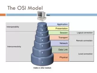
The OSI Model • Model for understanding and developing network computer-to-computer communications • Developed by ISO in the 1980s • Divides network communications into seven layers • Physical, Data Link, Network, Transport, Session, Presentation, Application • Protocol interaction • Layer directly above and below • Application layer protocols • Interact with software • Physical layer protocols • Act on cables and connectors What is the OSI?Demo
The OSI Model (cont’d.) • Theoretical representation describing network communication between two nodes • Hardware and software independent • Every network communication process represented • PDUs (protocol data units) • Discrete amount of data • Application layer function • Flow through layers 6, 5, 4, 3, 2, and 1 • Generalized model and sometimes imperfect Flow of data through the OSI model
The OSI Model Overview of Layered Architecture Demo
The OSI Model The layers of the model Demo • The Application, Presentation and Session layers are known as the Upper Layers and are implemented in software • The Transport and Network layer are mainly concerned with protocols for delivery and routing of packets and are implemented in software as well • The Data Link is implemented in hard- and software • The Physical layer is implemented in hardware only, hence its name. These lower two layers define LAN and WAN specifications. Upper Layers Demo Lower Layers Demo
The OSI Model • A more detailed description of each layer follows later, but here's what basically happens when data passes from Host A to Host B: • The Application, Presentation and Session layers take user input and converts it into data • The Transport layer adds a segment header converting the data into segments • The Network layer adds a network header and converts the segments into packets / datagrams • The Data Link layer adds a frame header converting the packets/datagrams into frames, the MAC sublayer converts the frames into bits, which the Physical layer can put on the wire. • These steps are known as dataencapsulation.
Packet Assembly and Disassembly Process • Each successive layer adds formatting and peer control information to the data in the form of a header. At the receiving end the headers are stripped off by the corresponding layers to determine how to handle the data. At the Data Link layer an error checking mechanism known as the Frame check sequence is added as a trailer. • When the bits stream arrives at the destination, the process is reversed and each layer will remove their corresponding header while the data flows up the OSI model until it is converted back to data and presented to the user. This is also known as decapsulation. Destination Computer Source Computer
Application Layer • Top (seventh) OSI model layer • Window to network services • Does not include software applications • Protocol functions • Facilitates communication between software applications and lower-layer network services • Network interprets application request • Application interprets data sent from network
Application Layer • Software applications negotiate with application layer protocols • Application program interface (API): set of routines that make up part of a software application • Formatting, procedural, security, synchronization, and other requirements • Examples of Application layer protocol: • HTTP, FTP and TFTP • SNMP and Telnet • DHCP and DNS • SMTP, POP and IMAP Application layer functions while retrieving a Web page The Application Layer Demo
Presentation Layer • Presentation Layer (6) • Network translator • Protocol functions • Accept Application layer data • Format data • Understandable to different applications and hosts • Examples of file types translated at the presentation layer • GIF, JPG, TIFF, MPEG, QuickTime, MIME and ASCII
Presentation Layer • Presentation layer services manage data compression, encryption and decryption • Example protocol: Secure Sockets Layer (SSL) • I/O redirectors work to redirect resources to a server • The Server and Workstation Services work at this layer Presentation layer services while retrieving a secure Web page The Presentation Layer Demo
Session Layer • Session Layer (5) • Protocol functions • Coordinate and maintain communications between two network nodes • Examples of protocols/API's that operate on this layer are RPC and NETBIOS. • Session • Connection for ongoing data exchange between two parties • Connection between remote client and access server • Connection between Web browser client and Web server
Session Layer • Functions • Establishing and keeping alive communications link • For session duration • Keeping communications secure • Synchronizing dialogue between two nodes • Determining if communications ended • Determining where to restart transmission by placing checkpoints in the data stream • Terminating communications • Set terms of communication • Decides which node will communicate first • Decides how long a node can communicate • Identify session participants Session layer protocols managing voice communications The Session Layer Demo
Transport Layer • Protocol functions • Accept data from Session layer • Manage end-to-end data delivery • Ensure data transferred reliably and without errors through sequencing and acknowledgements. • Handle flow control • Connection-oriented protocols • TCP & SPX • Establish connection before transmitting data • Example: TCP three-way handshake • SYN (synchronization) packet • Client’s TCP protocol first sends synchronization (SYN) packet request to server • SYN-ACK (synchronization-acknowledgment) • Server responds with synchronization-acknowledgment (SYN-ACK) packet • ACK • Client responds with own acknowledgment (ACK)
Transport Layer (cont’d.) • Checksum • Unique character string • Allows receiving node to determine if arriving data matches sent data • Connectionless protocols • UDP • Do not establish connection with another node before transmitting data • Do not check for data integrity • Faster than connection-oriented protocols
Transport Layer (cont’d.) • Segmentation • Breaking large data units received from Session layer into multiple smaller units called segments • Increases data transmission efficiency on certain network types • MTU (maximum transmission unit) • Largest data unit network will carry • Ethernet default: 1500 bytes • Discovery routine used to determine MTU
Transport Layer (cont’d.) • Reassembly • Recombining the segmented data units • Sequencing • Identifying segments belonging to the same group of subdivided data • Specifies order of data issue Segmentation and reassembly The Transport Layer Demo
Network Layer • Protocol functions • Translate network addresses into physical counterparts • ARP • Decide how to route data from sender to receiver • RIP, OSPF, IGMP, BGP • Troubleshooting network connectivity • ICMP (Internet Control Message Protocol) • Ping and Tracert • Addressing • System for assigning unique identification numbers to network devices • Addresses the package using network address scheme (encapsulates into packets) • Types of addresses • Network addresses (logical or virtual addresses) • IP, IPX • Network address example: 10.34.99.12 • Physical addresses • Physical address example: 0060973E97F3
Network Layer (cont’d.) • Network layer handles routing • Common Network layer protocol • IP (Internet Protocol) • Determines the best route on the network • Factors used to determine path routing • Delivery priority • Network congestion • Quality of service • Cost of alternative routes • Routers belong in the network layer • Fragmentation • Subdividing Transport layer segments • Performed at the Network layer • Segmentation preferred over fragmentation for greater network efficiency The Network Layer Demo
Data Link Layer • Function of protocols • Divide data received into distinct frames for transmission in Physical layer (encapsulation) • Appends Physical address and Frame Check Sequence (FCS) to the frame • Frame • Structured package for moving data • Parts of data frame: Destination ID, Sender ID, Control Data • Includes raw data (payload), sender’s and receiver’s network addresses, error checking and control information
Data Link Layer (cont’d.) • Possible communication mishap • Not all information received • Corrected by error checking • Error checking accomplished by 4-byte Frame Check Sequence (FCS) field • Ensures data at destination exactly matches data issued from source • When source node transmits data, performs Cyclic Redundancy Check (CRC) to get FCS • Destination node’s Data Link layer services unscramble FCS via same CRC algorithm • Possible glut of communication requests • Data Link layer controls flow of information • Allows NIC to process data without error
Data Link Layer (cont’d.) • Two Data Link layer sublayers • LLC (Logical Link Control) sublayer • Provides a common interface to the Network Layer, reliability and flow control • Defines SAPs (Service Access Points) • MAC (Media Access Control) sublayer • NDIS works at this level • Manages access to the physical medium • Defines IEEE LAN standards such as 802.3, 802.4, 802.5, and 802.11 • Converts the frames into bits and puts them on the wire • Appends physical address of destination computer onto data frame • Physical (MAC) address • Fixed number associated with each device’s network interface
A NIC’s physical address A NIC’s MAC address contains two parts: a block ID and a device ID. The block ID is a six-character sequence unique to each vendor. The remaining six characters known as the device ID are added at the factory, based on the NIC’s model and manufacture date. The Data Link Layer Demo
Physical Layer • Functions of protocols • Accept frames from Data Link layer • Generate signals as changes in voltage at the NIC • Data sent as an unstructured raw bit stream over physical medium • Defines how the cable is attached to the NIC • Copper transmission medium • Signals issued as voltage • Fiber-optic cable transmission medium • Signals issued as light pulses • Wireless transmission medium • Signals issued as electromagnetic waves
Physical Layer (cont’d.) • Physical layer protocols’ responsibilities when receiving data • Detect and accept signals • Pass on to Data Link layer • Set data transmission rate • Monitor data error rates • No error checking • Devices operating at Physical layer • Hubs and repeaters • NICs operate at both Physical layer and Data Link layers • Network administrators mostly concerned with bottom four layers of OSI Model The Physical Layer Demo
Applying the OSI Model Functions of the OSI layers The OSI Model in the Real World (6:00)
Communication Between Two Systems • Data transformation • Original software application data differs from application layer NIC data • Information added at each layer • PDUs • Generated in Application layer • Segments • Generated in Transport layer • Unit of data resulting from subdividing larger PDU Data transformation through the OSI Model
Communication Between Two Systems • Packets • Generated in Network layer • Data with logical addressing information added to segments • Frames • Generated in Data Link layer • Composed of several smaller components or fields • Encapsulation • Occurs in Data Link layer • Process of wrapping one layer’s PDU with protocol information • Allows interpretation by lower layer • Physical layer transmits frame over the network Data transformation through the OSI Model
Frame Specifications • Frames • Composed of several smaller components or fields • Frame characteristic dependencies • Network type where frames run • Standards frames must follow • Ethernet • Developed by Xerox • Four different types of Ethernet frames • Most popular: IEEE 802.3 standard • Token ring • Developed by IBM • Relies upon direct links between nodes and ring topology • Nearly obsolete • Defined by IEEE 802.5 standard • Ethernet frames and token ring frames differ • Will not interact with each other • Devices cannot support more than one frame type per physical interface or NIC
IEEE Networking Specifications • IEEE’s Project 802 • Effort to standardize physical and logical network elements • Frame types and addressing • Connectivity • Networking media • Error-checking algorithms • Encryption • Emerging technologies • 802.3: Ethernet • 802.5: Token Ring • 802.11: Wireless Network Standards Demo
IEEE Networking Specifications IEEE 802 standards
Summary • Standards are documented agreements containing precise criteria that are used as guidelines to ensure that materials, products, processes, and services suit their purpose • ISO’s OSI Model divides networking architecture into seven layers • Each OSI layer has its own set of functions and interacts with the layers directly above and below it • Application layer protocols enable software to negotiate their formatting, procedural, security, and synchronization with the network
Summary (continued) • Presentation layer protocols serve as translators between the application and the network • Session layer protocols coordinate and maintain links between two devices for the duration of their communication • Transport layer protocols oversee end-to-end data delivery • Network layer protocols manage logical addressing and determine routes based on addressing, patterns of usage, and availability • Data Link layer protocols organize data they receive from the Network layer into frames that contain error checking routines and can then be transmitted by the Physical layer • Physical layer protocols generate and detect voltage to transmit and receive signals carrying data over a network medium • Data frames are small blocks of data with control, addressing, and handling information attached to them