Download
1 / 13
130 likes | 536 Views
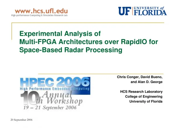
Experimental Analysis of Multi-FPGA Architectures over RapidIO for Space-Based Radar Processing. Chris Conger, David Bueno, and Alan D. George HCS Research Laboratory College of Engineering University of Florida. Project Overview.

E N D
Experimental Analysis of Multi-FPGA Architectures over RapidIO for Space-Based Radar Processing Chris Conger, David Bueno, and Alan D. George HCS Research Laboratory College of Engineering University of Florida
Project Overview • Considering advanced architectures for on-board satellite processing • Reconfigurable components (e.g. FPGAs) • High-performance, packet-switched interconnect • Sponsored by Honeywell Electronic Systems Engineering & Applications • RapidIO as candidate interconnect technology • Ground-Moving Target Indicator (GMTI) case study application • Design working prototype system, on which to perform performance and feasibility analyses • Experimental research, with focus on node-level design and memory-processor-interconnect interface architectures and issues • FPGAs for main processing nodes, parallel processing of radar data • Computation vs. communication: application requirements, component capabilities • Hardware-software co-design • Numerical format and precision considerations Image courtesy [5]
Background Information • RapidIO • Three-layered, embedded system interconnect • Point-to-point, packet-switched connectivity • Peak single-link throughput ranging from 2 to 64 Gbps • Available in serial or parallel versions, in addition to message-passing or shared-memory programming models Image courtesy [6] DATA-PARALLEL • Space-Based Radar (SBR) • Space environment places tight constraints on system • Frequency-limited radiation-hardened devices • Power- and memory-limited • Streaming data for continuous, real-time processing of radar or other sensor data • Pipelined or data-parallel algorithm decomposition • Composed mainly of linear algebra and FFTs • Transposes or distributed corner turns of entire data set required, stresses memory hierarchy • GMTI composed of several common kernels • Pulse compression, Doppler processing, CFAR detection • Space-Time Adaptive Processing and Beamforming PIPELINED
Testbed Hardware • Custom-built hardware testbed, composed of: • Xilinx Virtex-II Pro FPGAs (XC2VP20-FF1152-6), RapidIO IP cores • 128 MB SDRAM (8 Gbps peak memory bandwidth per-node) • Custom-designed PCBs for enhanced node capabilities • Novel processing node architecture (HDL) • Performance measurement and debugging with: • 500 MHz, 80-channel logic analyzer • UART connection for file transfer While we prefer to work with existing hardware, if the need arises we have the ability to design custom hardware RapidIO switch PCB RapidIO testbed, showing two nodes directly connected via RapidIO, as well as logic analyzer connections RapidIO testbed RapidIO switch PCB layout
Node Architecture • All processing performed via hardware engines, control performed with embedded PowerPC • PowerPC interfaces with DMA engine to control memory transfers • PowerPC interfaces with processing engines to control processing tasks • Custom software API permits app development • Visualize node design as a triangle of communicating elements: • External memory controller • Processing engine(s) • Network controller • Parallel data paths (FIFOs and control logic) allow concurrent operations from different sources • Locally-initiated transfers completely independent of incoming, remotely-initiated transfers • Internal memory used for processing buffers (no external SRAM) Conceptual diagram of FPGA design (node architecture)
Processing Engine Architectures • All co-processor engines wrapped in standardized interface (single data port, single control port) • Up to 32 KB dual-port SRAM internal to each engine • Entire memory space addressable from external data port, with read and write capability • Internally, SRAM divided into multiple, parallel, independent read-only or write-only ports • Diagrams below show two example co-processor engine designs, illustrating similarities CFAR Co-processor Architecture Pulse Compression Co-processor Architecture
Experimental Environment • System and algorithm Parameters • Numerical Format • Signed magnitude, fixed-point, 16-bit • Complex elements for 32-bit/element • Experimental steps • No high-speed input to system, so data must be pre-loaded • XModem over UART provides file transfer between testbed and user workstation • User prepares measurement equipment, initiates processing after data is loaded through UART interface • Processing completes relatively quickly, output file is transferred back to user • Post-analysis of output data and/or performance measurements
Results: Baseline Performance • Data path architecture results in independent clock domains, as well as varied data path widths • SDRAM: 64-bit, 125 MHz (8 Gbps max theoretical) • Processors: 32-bit, 100 MHz (4 Gbps max theoretical) • Network: 64-bit, 62.5 MHz (4 Gbps max theoretical) • Generic data transfer tests to stress each communication channel, measure actual throughputs achieved • Notice transfers never achieve over 4 Gbps • “A chain is only as strong as its weakest link” • Simulations of custom SDRAM controller core alone suggest maximum sustained* throughput of 6.67 Gbps Max. sustained* throughputs • SDRAM: 6.67 Gbps • Processor: 4 Gbps • Network: 3.81 Gbps SRAM-to-FIFO, so processor transfers achieve 100% efficiency; latency negligible * Assumes sequential addresses, data/space always available for writes/reads 20 September 2006 8
Results: Kernel Execution Time • Processing starts when all data is buffered • No inter-processor communication during processing • Double-buffering maximizes co-processor efficiency • For each kernel, processing is done along one dimension • Multiple “processing chunks” may be buffered at a time: • CFAR co-processor has 8 KB buffers, all others have 4 KB buffers • CFAR works along range dimension (1024 elements or 4 KB) • Implies 2 “processing chunks” processed per buffer by CFAR engine • Single co-processing engine kernel execution times for an entire data cube • CFAR only 15% faster than Doppler processing, despite 39% faster buffer execution time • Loss of performance for CFAR due to under-utilization • Equation to lower right models execution time of an individual kernel to process an entire cube (using double-buffering) • Kernel execution time can be capped by both processing time as well as memory bandwidth • After certain point, higher co-processor frequencies or more engines per node will become pointless PC = Pulse Compression DP = Doppler Processing
Results: Data Verification • Processed data inspected for correctness • Compared to C version of equivalent algorithm from Northwestern University & Syracuse University [7] • MATLAB also used for verification of Doppler processing and pulse compression engines • Expect decrease in accuracy of results due to decrease in precision • Fixed-point vs. floating-point • 16-bit elements vs. 32-bit elements • CFAR and Doppler processing results shown to right, along-side “golden” or reference data • Pulse compression engine very similar to Doppler processing, results omitted due to space limitations • CFAR detections suffer significantly from loss of precision • 97 detected (some false), 118 targets present • More false positives where values are very small • More false negatives where values are very larger • Slight algorithm differences prevent direct comparison of Doppler processing results with [7] • MATLAB implementation and testbed both fed square wave as input • Aside from expected scaling in testbed results, data skewing can be seen from loss of precision
Results: FPGA Resource Utilization • FPGA resource usage table* (below) • Virtex-II Pro (2VP40) FPGA is target device • Baseline design includes: • PowerPC, buses and peripherals • RapidIO endpoint (PHY + LOG) and endpoint controller • SDRAM controller, FIFOs • DMA engine and control logic • Single CFAR co-processor engine • Co-processor engine usage* (right) • Only real variable aspect of design • Resource requirements increase with greater data precision * Resource numbers taken from mapper report (post-synthesis)
Conclusions and Future Work • Novel node architecture introduced and demonstrated • All processing performed in hardware co-processor engines • Apps developed in Xilinx’s EDK environment using C, custom API enables control of hardware resources through software • External memory (SDRAM) throughput at each node is critical for system performance in systems with hardware processing engines and integrated high-performance network • Pipelined decomposition may be better for this system, due to co-processor (under)utilization • If co-processor engines sit idle most of the time, why have them all in each node? • With sufficient memory bandwidth, multiple engines could be used concurrently • Parallel data paths are nice feature, at cost of more complex control logic, higher potential development cost • Multiple request ports to SDRAM controller improves concurrency, but does not remove bottleneck • Different modules within design can request and begin transfers concurrently through FIFOs • SDRAM controller can still only service one request at a time (assuming one external bank of SDRAM) • Benefit of parallel data paths decreases with larger transfer sizes or more frequent transfers • Parallel state machines/control logic take advantage of FPGA’s affinity for parallelism • Custom design, not standardized like buses (e.g. CoreConnect, AMBA, etc) • Some co-processor engines could be run at slower clock rates to conserve power without loss of performance • 32-bit fixed-point numbers (possibly larger) required if not using floating-point processors • Notable error can be seen in processed data simply by visually comparing to reference outputs • Error will compound as data propagates through each kernel in a full GMTI application • Larger precision means more memory and logic resources required, not necessarily slower clock speeds • Future Research • Enhance testbed with more nodes, more stable boards, Serial RapidIO • Complete Beamforming and STAP co-processor engines, demonstrate and analyze full GMTI application • Enhance architecture with direct data path between processing SRAM and network interface • More in-depth study of precision requirements and error, along with performance/resource implications
Bibliography [1] D. Bueno, C. Conger, A. Leko, I. Troxel, and A. George, “Virtual Prototyping and Performance Analysis of RapidIO-based System Architectures for Space-Based Radar,” Proc. High Performance Embedded Computing (HPEC) Workshop, MIT Lincoln Lab, Lexington, MA, Sep. 28-30, 2004. [2] D. Bueno, A. Leko, C. Conger, I. Troxel, and A. George, “Simulative Analysis of the RapidIO Embedded Interconnect Architecture for Real-Time, Network-Intensive Applications,” Proc. 29th IEEE Conf. on Local Computer Networks (LCN) via IEEE Workshop on High-Speed Local Networks (HSLN), Tampa, FL, Nov. 16-18, 2004. [3] D. Bueno, C. Conger, A. Leko, I. Troxel, and A. George, “RapidIO-based Space Systems Architectures for Synthetic Aperture Radar and Ground Moving Target Indicator,” Proc. Of High-Performance Embedded Computing (HPEC) Workshop, MIT Lincoln Lab, Lexington, MA, Sep. 20-22, 2005. [4] D. Bueno, C. Conger, and A. George, "RapidIO for Radar Processing in Advanced Space Systems," ACM Transactions on Embedded Computing Systems, to appear. [5] http://www.noaanews.noaa.gov/stories2005/s2432.htm [6] G. Shippen, “RapidIO Technical Deep Dive 1: Architecture & Protocol,” Motorola Smart Network Developers Forum, 2003. [7] A. Choudhary, W. Liao, D. Weiner, P. Varshney, R. Linderman, M. Linderman, and R. Brown, “Design, Implementation and Evaluation of Parallel Pipelined STAP on Parallel Computers,” IEEE Trans. on Aerospace and Electrical Systems, vol. 36, pp 528-548, April 2000.