Download
1 / 51
510 likes | 669 Views
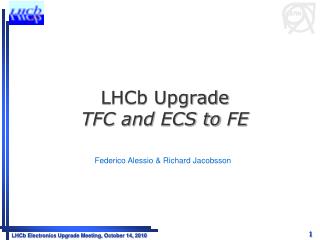
Running simulation for the Mini-DAQ: TFC and FE features. LHCb Electronics Upgrade Meeting 12 December 2013. Federico Alessio. Simulation framework. Generic FE Data Generator. FE data generator from user. ODIN 40. FE TFC data 84 bits. FE TFC data 84 bits. SOL 40. FE(s) data.

E N D
Runningsimulation for the Mini-DAQ: TFC and FE features LHCb Electronics Upgrade Meeting 12 December 2013 Federico Alessio
Simulationframework Generic FE Data Generator FE data generator from user ODIN 40 FE TFC data84 bits FE TFC data84 bits SOL 40 FE(s) data FE(s) data BE TFC data64 bits Throttle 64 bits Throttle File.txt Throttle resets x6 x6 Memory x6 x6 Data Generator from .txt file MEP building DataProcessing LLT decision x6 BCIDAlignment Decoding FE Interface (x6 inputs) - data_valid (1 bit) [output] - data (flexible width bus) [output] - ready (1 bit) [input] Computer Network 2
Simulationframework • Philosophymaintaned: • flexible, configurable, easy-to-use, collaborative … • Realistic and synthesizable code for TFC + TELL40 + MEP • realisticenvironment • followspecs to the verylast detail • expertise available for it • Emulation of differentallowed FE encodings • genericone • from a .txt file (raw data) • from you… 3
S-ODIN HDL code For details on S-ODIN, seeLHCb-PUB-2012-001 4
TFC (fast commands) available to TELL40 to FE Periodicity, rates, delays, codes are allconfigurable via a simpleconfiguration package For details on the commands and theirusage, seeLHCb-PUB-2012-017 5
Configuration package features I Everythingisexplained in the Mini-DAQ handbookdocument! Enables NZS triggers and Calibrationtypes 6
Configuration package features II Variousenables/parameters to emulate TFC commands to FE 7
Front-End HDL code • Implementedthreegenericdifferenttypes of algorithms to emulate FE data encoding: • Variable frame lengthpacking with Variablesizeheader (called VV) • Variable frame lengthpacking with Fixedsizeheader (called FV) • Fixed frame lengthpacking with Fixedsizeheader (called FF) • NB: thiswasneeded to develop the TELL40 code and studyeachdecoding scenario For more details, seeLHCb-INT-2013-015 8
Reminder: your (generic) FE NO TRIGGER to FE! Only commands, clock and slow control For details, see LHCb-INT-2011-011 • Compress (zero-suppress) data already at the FE • reduce # of links • data driven readout (asynchronous) + variable latencies! • Efficiently use data link bandwidth • pack data on data link continuously with elastic buffer • extensive use of GBT (robust FEC vsWideBus mode) • evaluate choices based on complexity vsrobustness 9
Reminder: generic FE data flow scheme Modify data according to TFC commands + BufferFullthen pack (continuously or not) onto GBT Tag data with TFC commands and pipe themacrosscompresson/suppressionlogicblock FE buffer for data Data availableneededonlyifcompression / suppressionisdynamic Applieschanges to data Compression/suppressionlogic can havedynamic or staticlatency 10
Variable frame lengthpackingalgorithm Average event size = link bandwidth Link bandwidth Average event size 0 1 2 3 4 0 1 2 3 4 0 1 2 3 4 = + Buffer depth • Asynchronous readout: header is the unique identifier for each event in frame: • Compulsory(tag for each crossing), partly programmable (mustcontain length of frame+BXID+info) • Difficult buffer management, but almost no truncation. • Flexible against occupancy fluctuation. Flexible usage of NZS data. • Maximum exploitation of bandwidth reduce # of links. • Readout Board uses Header info to decode and separate frames lots of resources. BX0 BX0 BX1 BX1 BX2 BX2 BX BX3 3 BX4 BX4 11
Dynamicpackingalgorithm Thisishow the FE buffer wouldbehave in this scenario (example with 500chx4bits + 12bits BXID + 1 «no data» bit BX VETO enabled for allempty-empty) Occupancy 3.6% Occupancy 3.5% Occupancy 3.4% Occupancy 3.3% Occupancy 3.2% Occupancy 3.1% 12
Fixed vs variablelengthheader in variable frame lengthpacking Variable packingwithfixedlength header (FV). Use case of this encoding is if FE occupancy is very low and want to save on # of links: less bits when no data is sent Variable packingwith variable length header (VV) (fully flexible!). 13
Fixed frame lengthpackingalgorithm Average event size /= link bandwidth Link bandwidth Average event size 0 1 2 3 4 0 1 2 3 4 0 1 2 3 4 = + Buffer depth • Synchronous readout: one clock cycle one event one GBT frame (for many FE ch) • Header more flexible: you can add addresses, hitmaps… Always at the same place. • Very simple buffer management, but truncation might happen(depends on avg event size) • Not flexible against occupancy problem (depends of avg event size). • Loses a bit of bandwidth as empty spaces must be padded. • Readout Board uses a fixed length to decode frames fewer resources BX0 BX0 BX1 BX1 BX2 BX2 BX3 BX3 BX4 BX4 14
Generic FE algorithms • Algorithms are generic and programmable via configuration package: • Programmable • Number of channel and size of channels • Buffer depth • GBT width frame (80 or 112 bits) • Headerfields • Introduce bugs in a controlled way • skip BXID, swap BXID etc… • Synthesizable • Estimate resources in FE (and TELL40…) • Can emulate ANYcombination of the FE packingalgorithms, • but must be compatible with TELL40 decoding… 15
Configuration package features III Everythingisexplained in the Mini-DAQ handbookdocument! Select the type of encoding + specifyheader and data fieldsparameters 16
Configuration package features IV Change the buffer depth, occupancy for differentchannels, alignmentsettings, pattern frame (rememberit’sprogrammable)… 17
Configuration package features V Introduce voluntarybugs in FE code 18
Nota Bene I • The FE encodings shown here are the ONLY ones allowed in the TELL40 decoding block • These has been agreed amongst you and if you want to perform a different type of encoding, you should contact us. • There are also other ways to inject FE data to test: • From a .txt file • From your own HDL code 19
Simulationframework Generic FE Data Generator FE data generator from user ODIN 40 FE TFC data84 bits FE TFC data84 bits SOL 40 FE(s) data FE(s) data BE TFC data64 bits Throttle 64 bits Throttle File.txt Throttle resets x6 x6 Memory x6 x6 Data Generator from .txt file MEP building DataProcessing LLT decision x6 BCIDAlignment Decoding FE Interface (x6 inputs) - data_valid (1 bit) [output] - data (flexible width bus) [output] - ready (1 bit) [input] Computer Network 20
Your FE code • Only specs: • FE data from a .txt file: • [112 or 80 bits data][1 bit data valid] • data valid = 1 == GBT data frame • data valid = 0 == GBT idle frame • FE data from your own code: • follow the allowed types of encoding Everythingisexplained in the Mini-DAQ handbookdocument! 21
Nota Bene II • We expect you to develop your code (eventually): • Use our configuration package’s constant declaration • In that way the entire simulation will be set up for you • Select the type of decoding and see if it works • There is a generic wave.do with the signals you are supposed to look at to figure out if it works or not • If it doesn’t, track a bug (and contact us) https://lbredmine.cern.ch/projects/amc40/issues/new 22
Outlook • Next steps: • FE code: Done! If you need help just ask. • TFC code: v0 is out there. • Will add more features to SODIN with time • Ask if you need to enable some features • Will work more on developing the SOL40 ECS code to FE • Help from CBPF to develop an emulation of the GBT-SCA • Collaboration with you and ESE group is fundamental (to say the least…) 23
Conclusion The simulation framework will be our tool to develop hardware code for the upgrade: Please use it, mis-use it and especially, contribute to it! We need all the expertise you can possibly provide. 24
(live) DEMOs 25
Qs & As? 26
The upgraded physical readout slice • Common electronicsboard for upgradedreadoutsystem: Marseille’s ATCA board with 4 AMC cards • S-ODIN AMC card • LLT AMC card • TELL40 AMC card • LHC Interfaces specific AMC card 27
Latest S-TFC protocol to TELL40 Wewillprovide the TFC decodingblock for the TELL40: VHDL entity with inputs/outputs • «Extended» TFC word to TELL40 via SOL40: • 64 bits sentevery 40 MHz = 2.56 Gb/s (on backplane) • packed with 8b/10b protocol(i.e. total of 80 bits) • no dedicated GBT buffer, use ALTERA GX simple 8b/10b encoder/decoder • MEP acceptcommandwhen MEP ready: • Take MEP address and pack to FARM • No need for special address, dynamic Constant latency after BXID • THROTTLE information from each TELL40 to SOL40: • no change: 1 bit for each AMC board + BXID for which the throttlewas set • 16 bits in 8b/10b encoder • same GX buffer asbefore (assame decoder!) 28
S-TFC protocol to FE, no change • TFC word on downlink to FE via SOL40 embedded in GBT word: • 24 bits in each GBT frame every 40 MHz = 0.98 Gb/s • allcommandsassociated to BXID in TFC word • Put localconfigurabledelays for each TFC command • GBT doesnotsupportindividualdelays for each line • Need for «local» pipelining: detector delays+cables+operationallogic (i.e. laser pulse?) • DATA SHOULD BE TAGGED WITH THE CROSSING TO WHICH IT BELONGS! • TFC word willarrivebefore the actualeventtakesplace • To allow use of commands/resets for particularBXID • Accounting of delays in S-ODIN: for now, 16 clock cyclesearlier + time to receive • Aligned to the furthest FE (simulation, then in situ calibration!) • TFC protocol to FE hasimplications on GBT configuration and ECS to/from FE • seespecsdocument! 29
Timing distribution • From TFC point of view, weensureconstant: • LATENCY: Alignment with BXID • FINE PHASE: Alignment with best samplingpoint • Some resynchronizationmechanismsenvisaged: • Within TFC boards • With GBT • No impact on FE itself • Loopbackmechanism: • re-transmit TFC word back • allows for latencymeasurement + monitoring of TFC commands and synchronization 30
How to decode TFC in FE chips? FE electronicblock • Use of TFC+ECS GBTsin FE is 100% common to everybody!! • dashedlines indicate the detector specificinterfaceparts • pleasepayparticular care in the clock transmission: the TFC clock must be used by FE to transmit data, i.e. lowjitter! • Kaptoncable, crate, copperbetween FE ASICs and GBTX 31
The TFC+ECS GBT Clock[7:0] External clock reference FEModule • These clocks should be the main clocks for the FE • 8 programmablephases • 4 programmablefrequencies (40,80,160,320 MHz) E – Port GBTX e-Link Phase - Shifter CLK Reference/xPLL E – Port FEModule E – Port ePLLRx GBTIA DEC/DSCR CDR E – Port data-down data-up Phase – Aligners + Ser/Des for E – Ports CLK Manager clock 80, 160 and 320 Mb/s ports GBLD SCR/ENC SER E – Port ePLLTx FEModule E – Port E – Port • Used to: • sample TFC bits • drive Data GBTs • drive FE processes Control Logic Configuration (e-Fuses + reg-Bank) one 80 Mb/s port GBT – SCA JTAG I2C Slave I2C Master E – Port data I2C (light) control clocks JTAG port I2C port 32
The TFC+ECS GBT protocol to FE • TFC protocolhasdirectimplications in the way in which GBT should be usedeverywhere • 24 e-links @ 80 Mb/s dedicated to TFC word: • use 80 MHz phaseshifter clock to sample TFC parallel word • TFC bits are packed in GBT frame so thattheyall come out on the same clock edge • We can repeat the TFC bits also on consecutive 80 MHz clock edgeifneeded • Leftover 17 e-linksdedicated to GBT-SCAs for ECS configuring and monitoring(seelater) 33
Words come out from GBT at 80 Mb/s • In simplewords: • Odd bits of GBT protocol on risingedgeof 40 MHz clock (first, msb), • Even bits of GBT protocol on fallingedgeof 40 MHz clock (second,lsb) 34
TFC decoding at FE after GBT • Thisiscrucial!! • wecan alreadyspecifywhereeach TFC bit will come out on the GBT chip • thisis the only way in which FE designers stillhaveminimalfreedom with GBT chip • if TFC info waspacked to come out on only 12 e-links (first oddtheneven), thendecoding in FE ASIC would be mandatory! • whichwouldmeanthatthe GBT bus wouldhave to go to each FE ASIC for decoding of TFC command • thereisalso the idea to repeat the TFC bits on even and odd bits in TFC protocol • wouldthat help? • FE couldtielogicalblocksdirectly on GBT pins… 35
Now, what about the ECS part? • Eachpair of bit from ECS field inside GBT can go to a GBT-SCA • OneGBT-SCA isneeded to configure the Data GBTs(EC one for example?) • The rest can go to either FE ASICs or DCS objects(temperature, pressure) via other GBT-SCAs • GBT-SCA chip hasalreadyeverything for us: interfaces, e-linksports .. • No reason to go for somethingdifferent! • However, «silicon for SCA will come laterthansilicon for GBTX»… • Weneedsomethingwhilewewait for it! 36
SOL40 encoding block to FE! • Protocol drivers build GBT-SCA packets with addressing scheme and bus type for associated GBT-SCA user busses to selected FE chip • Basically each block will build one of the GBT-SCA supported protocols Memory Mapwith internal addressing scheme for GBT-SCA chips + FE chips addressing, e-link addressing and bus type: content of memory loaded from ECS 37
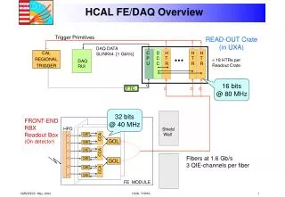
Fast & Slow Control to FE TFC TFC 4.8 Gb/s On detector Off detector ECS 4.8 Gb/s ECS Data Off detector Data 4.8 Gb/s • Separate links between controls and data • A lot of data to collect • Controls can be fanned-out (especially fast control) • Compact links merging Timing, Fast and Clock (TFC) and Slow Control (ECS). • Extensive use of GBT as Master GBT to drive Data GBT(especially for clock) • Extensive use of GBT-SCA for FE configuration and monitoring 38
The code: GBT dynamicpacking Very important to analyze simulation output bit-by-bit and clock-by-clock! 41
Studieddifferences in efficiency This is the usual example: 500 channels of 4 bits each, occupancy 3.1%, buffer depth 160, 12 bits of BXID Dynamic with dynamic header Buffer occupancy over 500 us Dynamic with fixed header 42
Studieddifferences in efficiency This is just another example: 500 channels of 4 bits each, occupancy 3.6%, buffer depth 160, 4 bits of BXID Dynamic with dynamic header Buffer occupancy over 500 us Dynamic with fixed header 43
Comparedresourcesneeded for differentencodings This is for the ENCODING. This is per GBT link! Logical Cells Variable encoding might help you save in fibers, but the cost will rise in FPGA/ASICs resources! 44
Comparedresourcesneeded for differentencodings This is for the ENCODING. This is per GBT link! Logical Cells NB: Fixed encoding is 460 LC! 10-100x less CALO & MUON use case - they need fixed latency for the LLT! 45
Studied impact on TELL40 resources This is for the DECODER in TELL40. 46
Studied impact on TELL40 resources Length field will likely contain the number of channels hit (not the length of the data word – that would require more bits) Each channel has a “data length unit value” (i.e. size of each channel) Ex: Length (8 bits) is 0x0A = 10 If data length unit value = 1 : real data length = 10bits If data length unit value = 4 : real data length = 40bits If data length unit value = 8 : real data length = 80bits The data length unit value should be bigger or equal to 4. Weshouldforbidsmallerthan 4. Test done with dynamic packing with dynamic header 47
The code: configuration • FE generic data generator is fully programmable: • Number of channels associated to GBT link • Width of each channel • Derandomizer depth • Mean occupancy of the channels associated to GBT link • Size of GBT frame (80 bits or WideBus + GBT header 4 bits) • Extremely flexible and easy to configure with parameters • Covers almost all possibilities (almost…) • Including flexible transmission of NZS and ZS • Including TFC commands as defined in specs • Study dependency of FE buffer behaviour with TFC commands • Study effect of packing algorithm on TELL40 • Study synchronization mechanism at beginning of run • Study re-synchronization mechanism when de-synchronized • Etc… etc… etc… • And it is fully synthesizable… 48
Conclusions • Packing mechanism as specified in our document is feasible. • Will be used temporarily to emulate FE generated data in global readout and TFC simulation. • However, very big open questions: • Is your FE compatible with such scheme? What about such code in an ASIC? • Behaviour of FE derandomizer will strongly depend on your compression or suppression mechanism. • If dynamic could create big latencies • If your data does not come out of order can become quite complicated… • Behaviour of FE derandomizer will strongly depend on TFC commands • FE buffer depth should not rely on having a BX VETO! Aim at a bandwidth for fully 40 MHz readout BX VETO solely to discard events synchronously. • What about SYNCH command? When do you think you can apply it? Ideally after derandomizer and after suppression/compression, but… • How many clock cycles do you need to recover from an NZS event? • Can you handle consecutive NZS events? 49
Old TTC systemsupport and runningtwosystems in parallel • We already suggested the idea of a hybrid system: • reminder: L0 electronics relying on TTC protocol • part of the system runs with old TTC system • part of the system runs with the new architecture • How? • Need connection between S-ODIN and ODIN (bidirectional) • use dedicated RTM board on S-ODIN ATCA card • In an early commissioning phase ODIN is the master, S-ODIN is the slave • S-ODIN task would be to distribute new commands to new FE, to new TELL40s, and run processes in parallel to ODIN • ODIN tasks are the ones today + S-ODIN controls the upgraded part • In this configuration, upgraded slice will run at 40 MHz, but positive triggers will come only at maximum 1.1MHz… • Great testbench for development + tests + apprenticeship… • Bi-product: improve LHCb physics programme in 2015-2018… • 3. In the final system, S-ODIN is the master, ODIN is the slave • ODIN task is only to interface the L0 electronics path to S-ODIN and to • provide clock resets on old TTC protocol 50