Download
1 / 13
140 likes | 472 Views
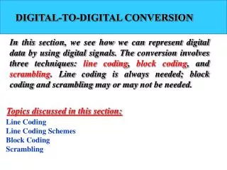
EE 552 High Level ASIC Design Using CAD Tools. Digital Theremin. Nicolas Lauzon Albert Ma Celia Valel. Farooq Ahmad Alesya Bajoria Tim Church . Introduction. The Theremin is a musical instrument invented in 1919 by Russian physicist Lev Termen.

E N D
EE 552 High Level ASIC Design Using CAD Tools DigitalTheremin Nicolas Lauzon Albert Ma Celia Valel Farooq Ahmad Alesya Bajoria Tim Church
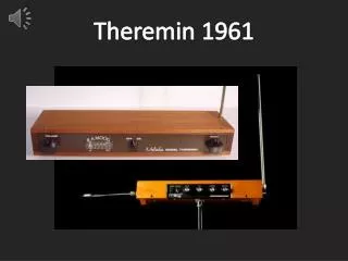
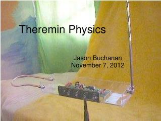
Introduction • The Theremin is a musical instrument invented in 1919 by Russian physicist Lev Termen. • Two antennas protrude from the Theremin – they use a variable capacitance to measure the proximity of the musician’s hands. • Approaching vertical antenna increases pitch while horizontal antenna controls volume. Traditional Theremin
Objective Our goal is the development of a digital instrument that can be played without direct contact. • VHDL and the XSA-100 Spartan-II Prototyping Board with XST-1 Xstend Protyping Extender Board were used. • IR sensors measured the distance of the musician’s hands from the instrument.
Hands can be moved from 10 cm to 80 cm from the sensors for volume and pitch control. Switches allow selection from various wave shapes: Features • Minimum frequency of 980 Hz and maximum frequency of 2.9 kHz. • Switch allows the musician to sustain a particular pitch.
Sustain Frequency Switch MC33172P Operational Amplifier Input Interface (serial-parallel conversion, ADC control) XSA-100 Spartan-II Prototyping Board GP2YOA21YK Distance Measuring Sensor (pitch) ADC974 Analog to Digital Converter (16-bit) Phase Accumulator Look Up Table (for frequency/ wave shape) selection Output Interface (parallel-serial conversion, Codec control) Volume Modulator GP2YOA21YK Distance Measuring Sensor (volume) Input Interface (serial-parallel conversion, ADC control) ADC974 Analog to Digital Converter (16-bit) 20-bit stereo audio codec to speaker MC33172P Operational Amplifier Wave Shape Selector Design Composed of three main components: 1. Input Interface 2. Numerically Controlled Oscillator 3. Output Interface
MC33172P Operational Amplifier Input Interface (serial-parallel conversion, ADC control) GP2YOA21YK Distance Measuring Sensor ADC974 Analog to Digital Converter (16-bit) Input Interface • Op-amp reduces loading. • Analog Devices AD974, converts analog output from the distance sensor to 16-bit serial data stream. • VHDL module controls ADC and converts its serial output to a parallel data vector to be used by the numerically controlled oscillator. • Sharp GP2Y0A21YK distance sensors measure proximity of hand by output of voltage from 2.5 V to 0.4 V as an object moves from 10 cm to 80 cm from it. -
Nonlinear output of distance measuring sensor was linearized using a VHDL module.
Numerically Controlled Oscillator • This component is responsible for outputting a sine, square, triangle or sawtooth wave of a frequency and amplitude controlled by the output of the IR sensors. • It consists of a: oPhase accumulator oWave look up table oVolume modulator
Phase Accumulator • The first stage of the NCO is a phase accumulator, which produces an output dependent on a parallel data word (proportional to the desired pitch) from the IR sensor. • A counter is increased in increments of this word, and wraps around every time it overflows. The numbers in the counter correspond to the phase of a sine wave increasing from 0 to 2*pi. The resulting wave shape is a wave with a frequency of fout = fclk x FCW/2j where fclk = the clock frequency, FCW = frequency control word from the IR sensor and j = size of frequency control word.
Wave Look-Up Table • The wave look up table will contain a single phase of each of the sine, sawtooth, triangle and square waves. • These values, which are stored for the use of the NCO, will be done so on the 40kbits of block RAM.
Volume Multiplier • The output from the distance measuring sensor responsible for volume control will be sent to a multiplier. • In this way, the amplitude of the output signal will be modified.
From NCO Output Interface (parallel-serial conversion, Codec control) To speaker 20-bit stereo audio codec Output Interface • The 16-bit parallel output from the volume modulator is converted into serial data. • This serial data will be fed to the 20-bit stereo codec which is present on the XST-2 XStend board. • The audio codec accepts the serial bit stream from the XS board and converts it to two analog output signals. • The signals are fed into an amplifier and output through a speaker.
Conclusions • This project has been successful in introducing a modern twist to an instrument that is has had an eighty-five year life span.