Download
1 / 25
260 likes | 536 Views
Object-Oriented Analysis. CIS 375 Bruce R. Maxim UM-Dearborn. OOA Tasks . Basic user requirements must be communicated between the customer and the software engineer. Classes must be identified (e.g. define attributes and methods) Specify class hierarchy

E N D
Object-Oriented Analysis CIS 375 Bruce R. Maxim UM-Dearborn
OOA Tasks • Basic user requirements must be communicated between the customer and the software engineer. • Classes must be identified (e.g. define attributes and methods) • Specify class hierarchy • Represent object-to-object relationships • Model object behavior • Reapply 1 through 5 iteratively until model is complete
OOA Generic Steps • Elicit customer requirements for system • Identify scenarios or use cases • Select classes and objects using basic requirements as a guide • Identify attributes and operations for each system object • Define structures and hierarchies that organize classes • Build object-relationship model • Build object-behavior model • Review OOA model against use-cases (scenarios)
Generic OOA Model - 1 • Static view of semantic classes • classes based on semantics of customer requirements • Static view of attributes • attributes describe classes • suggest operations relevant to classes • Static view of relationships • represent relationships in a way that allows identification of operations and the design of a messaging approach
Generic OOA Model - 2 • Static view of behaviors • behaviors accommodating system usage scenarios implemented by sequences of operations • Dynamic view of communication • among objects • based on events that cause state transitions • Dynamic view of control and time • describe the nature and timing of events causing state transitions
Unified Modeling Language (UML) Elements - 1 • User model view • describes usage scenarios from the end-user's perspective • Structural model view • static structure of data and functionality is modeled (classes, objects, relationships) • Behavioral model view • represents dynamic system aspects • interactions or collaborations between structural elements in the user and structural models
Unified Modeling Language (UML) Elements - 2 • Implementation model view • representing the structural and behavioral aspects of the system as they are to be built • Environment model view • representation of the structural and behavioral aspects of the environment in which the system will be implemented
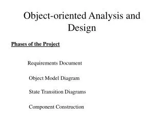
Simplified OOA Modeling - 1 • Class or Object Modeling • build an object model using ER diagram or • UML class diagrams • Scenario-Based Modeling • Use case stories or • UML use case diagrams • UML activity diagrams
Simplified OOA Modeling - 2 • Dynamic or Behavior Modeling • build a finite state machine type model or • UML state diagram • UML collaboration diagram • Functional Modeling • similar to data flow diagram • UML collaboration diagram
Domain Analysis • Define the domain to be investigated • Categorize the items extracted from the domain • Collect a representative sample of applications in the domain • Analyze each application in the sample • Develop an analysis model for the objects
Analysis of Applications • Identify candidate reusable objects • Indicate reasons the objects may be reused • Define adaptations of the objects that may be reused • Estimate percentage of applications in the domain that might make reuse of the objects • Identify objects by name and use configuration management techniques to control them
Use Case Objectives • Define the functional and operational requirements of system by defining a scenario of usage agreed upon by the end-user and software engineer • Provide an unambiguous description of how the end-user and system interact with one another • Provide a basis for validation testing
Class-Responsibility-Collaborator (CRC) Modeling • Develop a set of index cards that represent the system classes • One class per card • Cards are divided into three sections • class name • class responsibilities • class collaborators • Once a complete CRC card set is developed it is reviewed examining the usage scenarios
Reviewing CRC Models - 1 • Each review participant is given a subset of the CRC cards (collaborating cards must be separated) • All use-case scenarios and use-case diagrams should be organized into categories • Review leader chooses a use-case scenario and begins reading it out loud • Each time a named object is read a token is passed to the reviewer holding the object's card
Reviewing CRC Models - 2 • When the reviewer receives the token, he or she is asked to describe the responsibilities listed on the card • The group determines whether one of the responsibilities on the card satisfy the use-case requirement or not • If the responsibilities and collaborations on the index card cannot accommodate the use-case requirements then modifications need to be made to the card set
Criteria CRC Class Inclusion • Class information (data) should be retained • Class Provides needed services • Contains multiple attributes • Common set of attributes apply to all object instances • Common set of operations apply to all object instances • External entities that produce or consume information
Allocating Responsibilities to Classes • Distribute system intelligence evenly • State each responsibility as generally as possible • Information and its related behaviors should reside within the same class • Localize all information about one entity in a single class • Share responsibilities among related classes when appropriate
Criteria for Defining Collaborators • Any time a class cannot fulfill a responsibility on its own it needs to interact with another class • A server object interacts with a client object to fulfill some responsibility
Deriving Object-Relationship Model • Using the CRC model a network of collaborators can be drawn • Reviewing the CRC model index card, responsibilities and collaborators are evaluated, each unlabeled connected line is named • Once the named relationships are established each end is evaluated to determine cardinality (0 to 1, 1 to 1, 0 to many, 1 to many) • Continue the process until a complete object-relationship model has been produced
Building has m floors n elevators Each floor has two buttons Class candidates Buttons. Elevators. Floor. Building. Movement. Illumination. Doors. Elevator Case Study
OOA Behavioral Model Construction • Evaluate all use-cases to understand the sequence of interaction within the system • Identify events that drive the interaction sequence and how events relate to specific objects • Create an event-trace for each use-case • Build a state transition diagram for the system • Review the object behavior model to verify accuracy and consistency