Download
1 / 30
300 likes | 745 Views
Outline. Object Oriented Concepts and principals Object Oriented AnalysisObject Oriented Design. OO Concepts and principals . . Introduction. We live in a world of objectsObject-Oriented view is an abstraction that models the world in ways that help us to better understand and navigate itOO approach was first proposed in the late 1960sAs time passes, object technologies are replacing classical software development approaches. Why?Object technologies lead to reuse, OO software is easier to9446

E N D
1. Object Oriented Analysis & Design
3. OO Concepts and principals
4. Introduction We live in a world of objects
Object-Oriented view is an abstraction that models the world in ways that help us to better understand and navigate it
OO approach was first proposed in the late 1960s
As time passes, object technologies are replacing classical software development approaches. Why?
Object technologies lead to reuse, OO software is easier to maintain, to adapt, and to scale.
5. OO Paradigm For many years, the term OO was used to denote a software development approach that used one of a number of OO programming languages(e.g. Ada 95, C++, Eiffel, Smalltalk)
Today, the OO paradigm encompasses a complete view of software engineering
Although any one of process models, could be adapted for use with OO, the best choice would be an evolutionary process model
6. The OO Process Model
7. OO Concepts Classes and class hierarchies
Instances
Inheritance
Abstraction and hiding
Objects
Attributes
Methods
Encapsulation
Polymorphism
Messages
8. Object
9. Polymorphism It is a characteristic that greatly reduces the effort required to extend an existing OO system.
Polymorphism enables a number of different operations to have the same name.
For example: drawing different type of graphs( e.g. Line, Pie, Histogram )
It decouples objects from one another making each more independent.
General class graph and one subclass for each type.
10. Messages
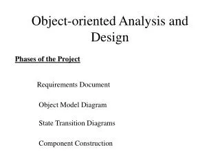
11. Object Oriented Analysis
12. Modeling Dimensions Identification/classification of entities.
General-to-specific and whole-to-part entity relationships
Other entity relationships
Description of attributes of entities
Large-scale model partitioning
States and transitions between states
Detailed specification for functions
Top-down decomposition
End-to-end processing sequences
Identification of exclusive services
Entity communications (via messages or events)
13. Conventional vs. OO Approaches Is OO analysis really different from the structured analysis approach?
A radical change over process oriented (SA).
An incremental change over data oriented methodologies (IE).
Structured Analysis (SA):
takes a distinct input-process-output view of requirements.
Data are considered separately from the processes that transform the data.
System behavior tends to play a secondary role.
makes heavy use of functional decomposition.
14. The OOA Landscape Dozens of OOA method during the late 1980s and into the 1990s are introduced.
Each of them proposed:
A process for the analysis of the product or system
A set of diagrams that evolved out of the process.
A notation that enabled the software engineer to create the analysis model in a consistent manner.
The most widely use were:
The Booch method ( an evolutionary approach is maintained).
The Rumbaugh method (Object modeling technique (OMT))
The Jacobson method (OO Software Engineering (OOSE))
The Coad and Yourdon method (One of the easiest)
The Wirfs-Brock method (do not make clear distinction between design and analysis tasks)
15. OOA & OOP OOA is based upon OOP: Classes and members, Objects and attributes and so on
To define them following tasks should be done:
Basic user requirements should be communicated between customer and software engineer
Classes must be identified
Class hierarchy should be specified
Object to object relationship should be presented
Object behavior should be modeled
These task should be reapplied iteratively until model is complete
16. Generic Steps for OOA Elicit customer requirements for the system.
Identify scenarios for use-cases.
Select classes and objects using basic requirements as a guide.
Identify attributes and operations for each system object.
Define structures and hierarchies that organize classes.
Build an object-behavior model.
Review the OO analysis model against use-cases or scenarios.
17. A Unified Approach to OOA Grady Booch, James Rumbaugh and Ivar Jacobson combine the best features into a unified method called:
Unified Modeling Language (UML)
UML allows a software engineer to express and analysis model using a modeling notation that is governed by a set of Syntactic, Semantic, and Pragmatic rules.
The syntax tells us how the symbols should look and how they are combined. (Word in natural language)
The semantics tells us what each symbols means and how it should be interpreted. (Meaning of words in natural language)
The pragmatic rules define the intentions of the symbols through which the perpose of the model is achieved and become understandable. (The rules for constructing sentences that are clear and understandable in natural language)
18. UML and Analysis Views User model view. This view represents the system (product) from the user�s (called �actors� in UML) perspective.
Structural model view. Data and functionality is viewed from inside the system. That is, static structure (classes, objects, and relationships) is modeled.
Behavioral model view. This part of the analysis model represents the dynamic or behavioral aspects of the system.
Implementation model view. The structural and behavioral aspects of the system are represented as they are to be built.
Environment model view. The structural and behavioral aspects of the environment in which the system is to be implemented are represented.
UML analysis modeling focuses on the first two views of the system.
UML design modeling addresses the other three views.
19. Domain Analysis OO Analysis can occur at many different levels of abstraction:
At the business or enterprise level
At the business area level
At an application level
OOA at the middle level called Domain Analysis.
Domain Analysis is performed to create a library of reusable classes applicable to an entire category of applications.
Using a robust class library produces the system faster, cheaper and more reliable.
But where did such a library come from? By applying domain analysis.
20. Domain Analysis Process The goal: to find or create those classes that are broadly applicable, so that they may be reused.
It can be viewed as an umbrella activity for the software process.
The role of domain analyst is to design and build reusable components that maybe used by many people working on similar but not necessarily the same applications.
Key inputs and outputs for the domain analysis process:
21. Domain Analysis Activities (1) Define the domain to be investigated.
Isolate the business area, system type, product category
Extract both OO and non-OO items.
OO-items such as: application and support (GUI, DB) classes, Commercial off-the-shelf (COTS) component libraries and test cases.
Non-OO items such as: policies, procedures, plans, standards and guidelines; parts of existing non-OO applications, metrics and COTS non-OO software.
Categorize the items extracted from the domain.
Organize items into categories.
Define the general defining characteristics of the categories.
Propose a classification scheme for the categories.
Define naming conventions for each item.
Establish classification hierarchy when appropriate.
22. Domain Analysis Activities (2) Collect a representative sample of applications in the domain.
Ensure that the application has items that fit into categories.
Analyze each application in the sample.
Identify candidate reusable objects.
Indicate the reasons that the object has been identified for reuse.
Define adaptions to the object that may also be reusable.
Estimate the percentage of applications in the domain that make reuse of the object.
Identify the object by name and use configuration management techniques to control them (chapter 9).
Develop an analysis model for the objects.
As a basis for design and construction of domain objects.
23. OOA- A Generic View define use cases
extract candidate classes
establish basic class relationships
define a class hierarchy
identify attributes for each class
specify methods that service the attributes
indicate how classes/objects are related
build a behavioral model
iterate on the first five steps
24. The OOA Process The OOA process begins with an understanding of the manner in which the system will be used by:
People, if the system is human-interactive.
Machines, if the system is involved in process control.
Programs, if the system coordinates and controls applications
Once the scenario of usage has been defined, the modeling of the software begins.
A series of techniques may be used to gather basic customer requirements.
25. Use Cases
26. Object Oriented Design
27. OOD OOD transforms the analysis model created using OOA into a design model that serves as a blueprint for software construction.
OOD results in a design that achieves a number of different levels of modularity.
Subsystems: Major system components.
Objects: Data and the operations.
Four important software design concepts:
Abstraction
Information Hiding
Functional Independence
Modularity
28. OOD The subsystem layer: Representation of each of the subsystems that enable the software to achieve its customer defined requirements.
The class and object layer: The class hierarchies, (generalization) and representation of objects.
The message layer: The design details of communication of each object with its collaborators. (external and internal interfaces)
The responsibilities layer: Data Structure and algorithmic design for all attributes and operations.
29. OOA to OOD
30. OOA to OOD
31. Design Issues decomposability�the facility with which a design method helps the designer to decompose a large problem into subproblems that are easier to solve;
composability�the degree to which a design method ensures that program components (modules), once designed and built, can be reused to create other systems;
understandability�the ease with which a program component can be understood without reference to other information or other modules;
continuity�the ability to make small changes in a program and have these changes manifest themselves with corresponding changes in just one or a very few modules;
protection�a architectural characteristic that will reduce the propagation of side affects if an error does occur in a given module.
32. Generic Components for OOD Problem domain component�the subsystems that are responsible for implementing customer requirements directly;
Human interaction component �the subsystems that implement the user interface (this included reusable GUI subsystems);
Task Management Component�the subsystems that are responsible for controlling and coordinating concurrent tasks that may be packaged within a subsystem or among different subsystems;
Data management component�the subsystem that is responsible for the storage and retrieval of objects.
33. Process Flow for OOD
34. System Design Process Partition the analysis model into subsystems.
Identify concurrency that is dictated by the problem.
Allocate subsystems to processors and tasks.
Develop a design for the user interface.
Choose a basic strategy for implementing data management.
Identify global resources and the control mechanisms required to access them.
Design an appropriate control mechanism for the system, including task management.
Consider how boundary conditions should be handled.
Review and consider trade-offs.
35. System Design
36. Subsystem Example
37. Subsystem Design Criteria The subsystem should have a well-defined interface through which all communication with the rest of the system occurs.
With the exception of a small number of �communication classes,� the classes within a subsystem should collaborate only with other classes within the subsystem.
The number of subsystems should be kept small.
A subsystem can be partitioned internally to help reduce complexity.
38. Subsystem Collaboration Table
39. Object Design A protocol description establishes the interface of an object by defining each message that the object can receive and the related operation that the object performs
An implementation description shows implementation details for each operation implied by a message that is passed to an object.
information about the object's private part
internal details about the data structures that describe the object�s attributes
procedural details that describe operations
40. Design Patterns add some example