Download
1 / 25
260 likes | 445 Views
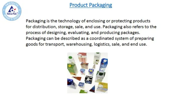
Packaging. Packaging Requirements. Desired package properties Electrical: Low parasitics Mechanical: Reliable and robust Thermal: Efficient heat removal Economical: Cheap. Wire bonding Only periphery of chip available for IO connections Mechanical bonding of one pin at a time (sequential)

E N D
Packaging Requirements Desired package properties • Electrical: Lowparasitics • Mechanical: Reliable and robust • Thermal: Efficient heat removal • Economical: Cheap • Wire bonding • Only periphery of chip available for IO connections • Mechanical bonding of one pin at a time (sequential) • Cooling from back of chip • High inductance (~1nH) More about packaging: http://www.embeddedlinks.com/chipdir/package.htm
Chip to package connection • Flip-chip • Whole chip area available for IO connections • Automatic alignment • One step process (parallel) • Cooling via balls (front) and back if required • Thermal matching between chip and substrate required • Low inductance (~0.1nH)
New package types • BGA (Ball Grid Array) • Small solder balls to connect to board • small • High pin count • Cheap • Low inductance • CSP (Chip scale Packaging) • Similar to BGA • Very small packages Package inductance: 1 - 5 nH
Package Types • Through-hole vs. surface mount From Adnan Aziz http://www.ece.utexas.edu/~adnan/vlsi-05/
Chip-to-Package Bonding • Traditionally, chip is surrounded by pad frame • Metal pads on 100 – 200 mm pitch • Gold bond wires attach pads to package • Lead frame distributes signals in package • Metal heat spreader helps with cooling From Adnan Aziz http://www.ece.utexas.edu/~adnan/vlsi-05/
Advanced Packages • Bond wires contribute parasitic inductance • Fancy packages have many signal, power layers • Like tiny printed circuit boards • Flip-chip places connections across surface of die rather than around periphery • Top level metal pads covered with solder balls • Chip flips upside down • Carefully aligned to package (done blind!) • Heated to melt balls • Also called C4(Controlled Collapse Chip Connection) From Adnan Aziz http://www.ece.utexas.edu/~adnan/vlsi-05/
Package Parasitics • Use many VDD, GND in parallel • Inductance, IDD From Adnan Aziz http://www.ece.utexas.edu/~adnan/vlsi-05/
L-C Oscillation f =1/(2p(LC)1/2) L = 10 nH C = 10 pF f = ~500MHz PCB trace Chip L Z C R Transmission line reflections Package Signal Interface • Transfer of IC signals to PCB • Package inductance. • PCB wire capacitance. • L - C resonator circuit generating oscillations. • Transmission line effects may generate reflections • Cross-talk via mutual inductance
Package Parameters 2000 Summary of Intel’s Package I/O Lead Electrical Parasitics for Multilayer Packages
Packaging Faults Small Ball Chip Scale Packages (CSP) Open
Packaging Faults CSP Assembly on 6 mil Via in 12 mil pad Void over via structure
Miniaturisation of Electronic Systems • Enabling Technologies : • SOC • High Density Interconnection technologies • SIP – “System-in-a-package” From ECE 407/507 University of Arizona http://www.ece.arizona.edu/mailman/listinfo/ece407
PCB scaling Advanced PCB Size scaling Laser via Interconnect Gap IC scaling Time The Interconnection gap • Improvement in density of standard interconnection and packaging technologies is much slower than the IC trends From ECE 407/507 University of Arizona http://www.ece.arizona.edu/mailman/listinfo/ece407
The Interconnection gap • Requires new high density Interconnect technologies PCB scaling Advanced PCB Size scaling Thin film lithography based Interconnect technology IC scaling Reduced Gap Time From ECE 407/507 University of Arizona http://www.ece.arizona.edu/mailman/listinfo/ece407
SoC has to overcome… • Technical Challenges: • Increased System Complexity. • Integration of heterogeneous IC technologies. • Lack of design and test methodologies. • Business Challenges: • Long Design and test cycles • High risk investment • Hence time to market. • Solution • System-in-a-Package From ECE 407/507 University of Arizona http://www.ece.arizona.edu/mailman/listinfo/ece407
Multiple Chip Module (MCM) • Increase integration level of system (smaller size) • Decrease loading of external signals > higher performance • No packaging of individual chips • Problems with known good die: • Single chip fault coverage: 95% • MCM yield with 10 chips: (0.95)10 = 60% • Problems with cooling • Still expensive