Download
1 / 30
300 likes | 417 Views
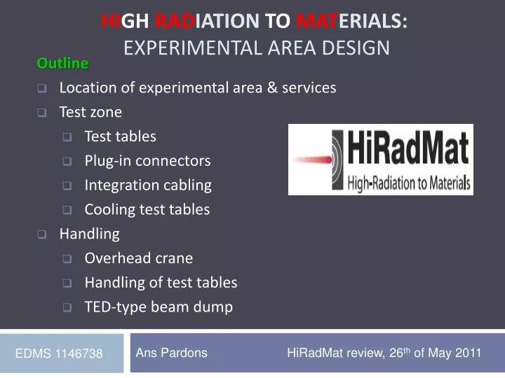
Outline Location of experimental area & services Test zone Test tables Plug-in connectors Integration cabling Cooling test tables Handling Overhead crane Handling of test tables TED-type beam dump. Hi gh Rad iation to Mat erials: EXPERIMENTAL Area DESIGN.

E N D
Outline • Location of experimental area & services • Test zone • Test tables • Plug-in connectors • Integration cabling • Cooling test tables • Handling • Overhead crane • Handling of test tables • TED-type beam dump High Radiationto Materials: EXPERIMENTAL Area DESIGN Ans Pardons HiRadMat review, 26th of May 2011 EDMS 1146738
Location of the experimental area Beam line elements Primary beam line Test tables Cooled collimator Cooled beam dump Beam direction Shielding To TCC6 TJ7 TNC TA7 10 m HiRadMat cool down zone for test tables Sarcophagus with WANF collimator blocks (2011) TNC Overhead crane (seen at downstream limit) All items in red will be treated in detail further-on
Location of test zone Test stands, services & monitoring in test zone Radiation Monitoring Beam Loss Monitors Beam Focal Points Test tables Monitoring • Directly on test table: • Cooling circuit (30kW, 3m3/h, 9bar) • Power (4 kV/2.5kA) • Signal cables (50V/2A e.g. for camera, motorization, vibration measurement ) Services available in irradiation area • In TA7- TJ7, at ~25m from test stands • - Overhead crane remote control • - Power (220V) • Patch panel in signal rack On passage-side wall opposite to test stand: - Gas connector for neutral gas (He or N2) All along TNC: - Lighting - Compressed air - Overhead crane
Test tables Mobile table: geometry and services 1 2 1 2 3 1 1 Mobile table Test object (e.g. LHC collimator) mounted on table as in lab 3 2 Connectors • Test table geometry • Mostly aluminium • Weight 450kg • Base plate 50mm thick • Available for test object: • Volume: 2 m x 0.7 m x (H) 1.5m (or cylinder of R=0.35m around beam) • Weight: 2000kg • Plug-in connectors • Remote handling with overhead crane • Test object mounted in surface lab
Table assembly 4 Base table with connectors 4 • In surface lab: dummy base table to mount and align test object and to test all connectors (copy of tunnel table) • In tunnel: same base table as surface lab – stays in tunnel and its position is checked yearly (and copied on surface) • Remote plug-in connector types • Cooling circuit (LHC collimator-type, “Staubli”) • Signal “type 1” (LHC collimator-type, “Hypertac”) • Power (SPS magnet-type) • Signal “type 2” (spare, SPS magnet-type) • Auto-aligned in tunnel
Table assembly in tunnel Integration in tunnel Installation of table is 100% remote (overhead crane & camera system) Tables compatible with different sizes and types of test objects Reminder: Test objects must be contained, cable feed-throughs and portholes must be tight (user’s design, with CERN approval) Cables arrive on the passage side and pass over to the test tables
Test tables Mechanical guides 1 1 2 2 3 3 • Base table: mechanical guides for remote installation • 3 V- shaped supports per mobile table (Extra V-shaped supports allow for different table sizes) • Lab-tested (<0.1mm), tunnel exercises planned
Test table connectors Signal “type 1” Signal “type 2” (spare) Power 4kV Cooling water Type 2 signal connector only on base table (seen as future upgrade for mobile tables) Power connector only on central table
Test table connectors Signal “type 1” connector box on mobile table b a c approach connected • Overview 3D-View of • mechanical guides, • water connector and • signal connector • Signal connector box • Burndy 28 pin round connector (F) • Burndy 50 pin rect. connector (F) • Coax BNC (F) • Replacement or repair • On mobile table (M) in surface lab • On base table (F): dismount connector locally as bloc and disconnect at 1.5m • Remote connection is lab-tested, exercises in tunnel planned
Integration cabling Coax CK50 (plug-in under development) Spare cables Cable guides: Structure for passage of cables / personnel / vehicles All cables from 3 test tables Quick connector (LHC collimator-type) at 1.5m from table for easier dismounting or cable exchange TNC 3 parallel cooling circuits TJ7
Integration cabling Cable guides • Cable guides: • Aluminium comb guides cables of all tables • Aluminium ramps and steel cover allow for safe passage • Cover and ramps in one piece, remote handling with magnetic lifting beam • Comb has hooks for remote dismantling
Integration cabling Racks near TJ7 TJ7 patch panel TNC Cables from TNC All cables from 3 test tables Rack in TJ7 Cables from BA7 To control room in BA7 front TJ7 cooling circuits Cooling circuit rack (flow meters, valves) where 3 parallel circuits join • At TJ7 patch panel: • Possibility for users to test connections and signals locally before start of beam (later no tunnel access • anymore and only observation from control room)
Integration cabling Control Room Cables from TJ7 patch panel Users Control Room Radioprotection Unit Room Entrance to HiRadMat BA7 Surface building Control room location in BA7 known, detailed study ongoing
Cooling test tables (more details in presentation of Paul Pepinster/Magali Mendez) TNC TJ7 Detection pressure drop safety valves close , 9 bar TA7 B. Lacarelle, Y. Lupkins Ans Pardons
Handling equipment Overhead crane TJ7 TNC • 7.5T suspended overhead crane with remote controller • Equipped with remote shielding block hook • Installed in 1994, completely renovated in 2010. • Extensive experience from WANF dismantling • Risk analysis done, followed by safety measures • Found to be very reliable
Handling equipment Remote viewing system TNC To material lift and BA7 TJ7 Set of 5 PZT optic fibre network cameras on crane frame(also on lifting beam) Cameras installed right before intervention Viewing station with 4 screens in TJ7
Handling of test tables Lab to test zone Custom-made trailer • From lab to test zone (non-radioactive object) • Surface lab: overhead crane to trailer • Trailer: from BA7 material lift TJ7 • TJ7: transfer to overhead crane • Remote with crane: TJ7 test zone in TNC
Handling of test tables Cool-down zone Downstream end of TNC • Test table supports • 100% Aluminium • Mechanical guides for remote installation (also remote dismantling) • Handling exercises in tunnel planned • Cool-down zone for test tables with test objects • Downstream in TNC, within reach of crane • 5 places (supports) foreseen for 2011, 3 more for 2012
Handling of test tables Test zone to cool-down zone • From test zone to cool-down zone (radioactive object) • Remote with crane: TJ7 cool-down zone in TNC • Remote with crane: place on cool-down zone supports
Handling of test tables Cool-down zone to surface • From cool-down zone to surface (radioactive object) • Remote, with crane: cool-down zone in TNC TJ7 • Remote, with crane: place on trailer • Manually, protected by distance (and shielding if needed):TJ7 material lift surface • Manually and in truck with container (and shielding if needed):surface CERN radioactive lab for disassembly • When needed, followed by waste disposal (CERN) • If dose rate negligible empty mobile table can be re-used
TED-type beam dump Geometry, Location and Handling • Beam dump exchange: 100% remote • Custom-made lifting beam • Pre-guiding upstream support • Guiding traces on shielding • Cameras on overhead crane • Procedures tested and optimized • Beam dump geometry and integration • Cooled and under nitrogen atmosphere (beam interlock)
High Radiationto Materials: EXPERIMENTAL Area DESIGN Thank you for your attention – Any questions?
Water connector – part 1 Seal = EPR (ethylene propylene rubber)
Power connector Material: Copper, aluminium (Antico 100), ceramic Mass: 3.3 kg for the fix part and 9.1 kg for the mobile part. Quantity: 2 (on table 2 only) Maximum current: 2.5kA, maximum voltage 4kV Maximum voltage: 4kV Available only on stand B. System: plug-in (standard SPS magnet supply).
Signal connector 50V (type 1) Material: Box: aluminuim EN AW-6082 Hypertac connectors : zamac and steel Screws: steel Cables : copper with kapton insulation (RadHard cabling) Maximum current: 3A Maximum voltage: 50V
Signal connector 50V (type 2) Material: Stainless steel: box, screws Insulating material (stumatite, kapton, glass fiber) Mass: 3.5 kg for the fixed part and 3.5 kg for the mobile part Maximum current: 2A Maximum voltage: 50V