Download
1 / 12
120 likes | 260 Views
Measurement report of Boostec girders Control after receipt. Measurements performed on the 1 st and 2 nd of December 2010 with the Laser Tracker LTD500. Plan. INTRODUCTION Tolerances to be checked Coordinates system Flatness and coaxiality 3079 girder 3069 girder Positioning

E N D
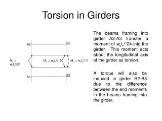
Measurement report of Boostec girdersControl after receipt Measurements performed on the 1st and 2nd of December 2010 with the Laser Tracker LTD500
Plan • INTRODUCTION • Tolerances to be checked • Coordinates system • Flatness and coaxiality • 3079 girder • 3069 girder • Positioning • 3079 girder • 3069 girder • Perpendicularity • CONCLUSION
INTRODUCTION The objective of the measurements is to perform the dimensional control of the 2 Boostec girders after receipt at CERN (building 162). We measured these girders according to Nicolas Chritin plans and tolerances (EDMS n° 1098660) using the Laser Tracker Leica LTD500. Measurement conditions were correct: temperature stability of 17.3°C to 17.8°C the 1st of December and of 17.1°C to 17.5°C the 2nd of December but lack of space. We will present measurement results with an accuracy of about 10 µm rms for the flatness and coaxiality and of about 20 µm rms for the positioning. We have not fully measured again Boostec girders but only checked the important points. The objectives were to check that girders were not damaged during transport and the machining of the side plans was consistent with the measurement report provided by Boostec (EDMS No. 1107158).
Tolerances to be checked General tolerances of ± 0.01 mm, *Tolerances of ± 0.1 mm
Coordinates system The coordinates system is the same that the one defined on site (EDMS n°1103378): _ Y axis = mean cylinders axis corrected by the offset generate by the cylinder diameter _ Z axis = perpendicular to the mean plane A _ System origin O = intersection of Y with the mean plane C
Flatness and coaxiality • 3079 girder • _ Planes flatness : • A : 18 µm rms • E : 9 µm rms • C : 4 µm rms • Bg : 2 µm rms • Bd : 6 µm rms • Fg : 6 µm rms • Fd : 4 µm rms • _ Axis coaxiality for the cylinder locations : 15 µm rms. • 3069 girder • _ Planes flatness : • A : 9 µm rms • E : 7 µm rms • C : 5 µm rms • Bg : 3 µm rms • Bd : 7 µm rms • Fg : 8 µm rms • Fd : 3 µm rms • _ Axis coaxiality for the cylinder locations : 8 µm rms. For the two Boostec girders, and with the consent of Nick Gazis, the planes D, H and I were not measured again.
Positioning • 3079 girder • _ Positioning of C with respect to E (along Y), distance between mean planes : 1946.073 mm or 73 µm of offset with respect to the nominal length. • _ Positioning of A with respect to Y axis (along Z): distance from the mean plane A to the Y axis of 528.935 mm or an offset of 65 µm (instead of 28µm on site). It will be necessary to measure this offset by CMM, the use of shims is possible. _ Positioning of Bg with respect to the median plane: -64.904 mm instead of -65 mm Positioning of Bd with respect to the median plane:64.974 mm pour 65 mm Positioning of Fg with respect to the median plane: -64.976 instead of -65 mm Positioning of Fd with respect to the median plane: 64.947 mm instead of 65 mm The Bd and Fd planes have been enough machined to allow the use of shims.
Positioning • 3069 girder • _ Positioning of C with respect to E (along Y), distance between mean planes : 1946.063 mm or 63 µm of offset with respect to the nominal length. • _ Positioning of A with respect to Y axis (along Z): distance from the mean plane A to the Y axis of 528.951 mm, or an offset of 49 µm (instead of 8µm on site). It will be necessary to measure this offset, if any, by CMM, the use of shims is possible. _ Positioning of Bg with respect to the median plane: -65.057 mm instead of -65 mm Positioning of Bd with respect to the median plane: 64.867 mm instead of 65 mm Positioning of Fg with respect to the median plane: -64.971 mm instead of -65 mm Positioning of Fd with respect to the median plane: 64.857 mm instead of 65 mm The Bg plane seems not to have been machined enough of the order of 60µm, the CMM measurements by Boostec confirm that (EDMSn°1107158).
Perpendicularity • 3079 and 3069 girders • For the two girders, and like on site, we have not detected any problem about perpendicularity between planes.
CONCLUSION • According to the results presented here and the accuracy of LTD500, we can confirm the measurements taken on site the 28th of October 2010 (EDMS No. 1103378) for the tolerances concerning : • Perpendicularities between planes, • Flatness of measured planes, • And the coaxiality of cylinders put on the V-supports. • For the positioning, we find offsets, for the two girders, of the order of 50µm between the bottom plane A and the beam axis. It will be necessary to check that with CMM measurements because these faults are above values detected on site, however it is possible to use shims. • The machining of the side planes seems to be enough to allow the use of shims, except for the Bg plan of the 3069 girder which is above about 50 µm (that is confirmed by CMM measurements of Boostec). More accurate measurements with CERN CMM will be necessary to define shims for the side planes. • The Boostec girders have apparently not been damaged during transport.