Download

1 / 20
290 likes | 541 Views
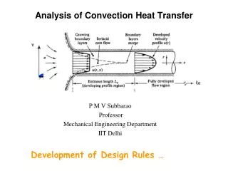
Analytical Modeling of Forced Convection in Slotted Plate Fin Heat Sinks. P. Teertstra, J. R. Culham & M. M. Yovanovich Microelectronics Heat Transfer Laboratory Department of Mechanical Engineering University of Waterloo Waterloo, Ontario, Canada http://www.mhtl.uwaterloo.ca.

E N D
Analytical Modeling of Forced Convection in Slotted Plate Fin Heat Sinks P. Teertstra, J. R. Culham & M. M. Yovanovich Microelectronics Heat Transfer Laboratory Department of Mechanical Engineering University of Waterloo Waterloo, Ontario, Canada http://www.mhtl.uwaterloo.ca Future Challenges in Electronic Packaging International ME’99 Congress and Exposition Nashville, TN November 17, 1999
Introduction: Plate Fin Heat Sinks • Heat transfer enhancement for air cooled applications: • increase effective surface area • decrease thermal resistance • control operating temperatures • Plate fin heat sinks: • most common configuration • convection in channels between fins
Introduction: Slotted Fin Heat Sinks • Enhanced thermal performance: • new thermal boundary layers initiated at each fin section • increase in average heat transfer coefficient • decrease in surface area • Performance of slotted fin heat sinks function of slot size and spacing • Optimal slotted fin heat sink design balances enhancement of h with reduction of A
Introduction: Heat Sink Selection • Heat sink selection depends on many factors: • performance • dimensional constraints • available airflow • cost • Quick and accurate design tools are required: • predict performance early in design • perform parametric studies • alternative to numerical simulations, experiments
Objectives • Develop analytical models for average heat transfer rate for slotted fin heat sinks: • laminar, forced convection flow • full range of developing and fully-developed flow • non-isothermal fins • Perform experimental measurements to validate proposed models: • range of slot sizes and spacing • inline and staggered slot arrangement
Problem Definition: Slotted Heat Sinks • Uniformly sized and spaced slots in fins • fins slotted from tip to baseplate • fin sections connected only by baseplate • Slot size and spacing described by dimensionless parameters: • pitch, • width, • Slot arrangement: • inline • staggered
Problem Definition: Plate Fin Heat Sink • Array of N plates on a single, flat baseplate • Baseplate assumptions: • fins in perfect thermal contact • isothermal • adiabatic lower surface, edges • Uniform velocity in all channels with no bypass: • shrouded heat sink • with flow bypass model for un-shrouded heat sinks • Heat sink modeled as N-1 parallel plate channels
Problem Definition: Parallel Plate Channel • Assume b << H • 2D channel flow • neglect baseplate, shroud effects • Isothermal boundary conditions • Reynolds number: • Nusselt number:
Parallel Plate Channel Model • Composite solution of 2 limiting cases (Teertstra et al, 1999) • Fully Developed Flow • Developing Flow
Plate Fin Heat Sink Model • Fin effects included in heat sink model: • high aspect ratio heat sinks for power electronics • dense arrays of tall, thin fins • increased surface area for convection • efficiency reduced • Fin efficiency: • Assume adiabatic condition at fin tip:
Plate Fin Heat Sink Model • Model Summary
Slotted Fin Heat Sink - Model Bounds • Complex problem where exact solution not possible • Upper and lower bounds from plate fin heat sink model:
Slotted Fin Heat Sink - Lower Bound • No new boundary layers formed • Modeled using equivalent fin length: • Lower bound expressions:
Slotted Fin Heat Sink - Upper Bound • New thermal boundary layer formed at each fin section with no upstream effects • Modeled using equivalent fin length: • Upper bound expressions:
Experimental Apparatus • High aspect ratio, • Various slot configurations • Back-to-back arrangement • Mounted in Plexiglas shroud • Approach velocity measured with hot wire anemometer • Temperatures measured at 4 locations on baseplate • Radiation losses measured in separate experiment
Model Validation • Arithmetic mean of bounds within 12% RMS of data
Summary and Conclusions • Models developed for upper and lower bounds for slotted fin heat sinks • Experimental data within bounds for full range of test conditions • Arithmetic mean of bounds predicts within 12% RMS over range of test conditions • Reliable optimization procedure cannot be determined from the limited range of values • Additional study and data are required
Acknowledgements The authors gratefully acknowledge the continued financial support of R-Theta Inc. and Materials and Manufacturing Ontario.