Download
1 / 33
330 likes | 336 Views
Cooling down of W7-X coils with/without casing circulation. 1. CICC coils experience. CICC conductors in fusion machines : EAST (in operation) KSTAR (in operation since 2008) W7-X (in construction) SST1 (in construction) JT-60SA (in construction) ITER (in construction). 2.

E N D
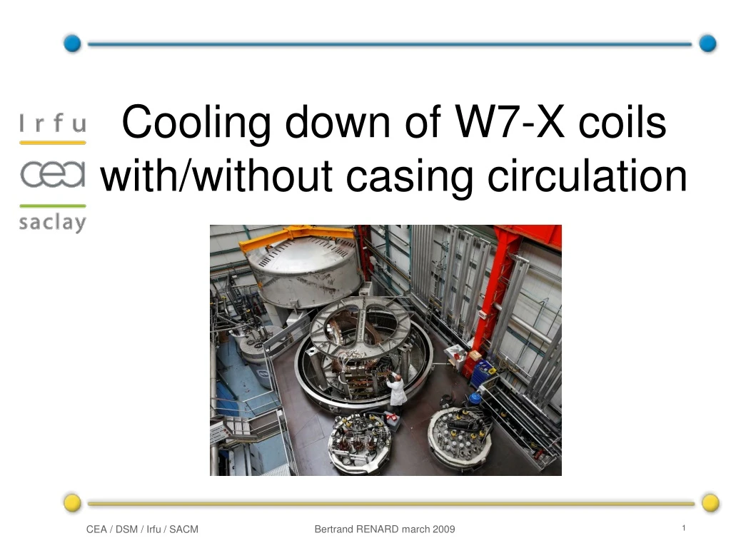
Cooling down of W7-X coils with/without casing circulation 1
CICC coils experience CICC conductors in fusion machines : • EAST (in operation) • KSTAR (in operation since 2008) • W7-X (in construction) • SST1 (in construction) • JT-60SA (in construction) • ITER (in construction) 2
1. Coil cooling down OUTLINE Description and limitations 2. Model of coil cooling Principle and comparison 3. Cooling down without casing circulation Cooling duration prevision 4. Current test without casing circulation Possibility to use nominal temperature and flow? 3
Coil cooling down: ramp AAB10, 11-20 July 2007, position 2A The inlet temperature rampreaches the limit of 2 K/h 4
Coil cooling down: mass flow rate m evaluated from ΔP and from the precise cryogenic measurement 5
Coil cooling down: maximum gradient ΔT in-out reaches the limit of 40 K on the casing 6
Coil cooling down: He power Power extraction through helium circulation 7
Coil cooling down: total power Total coil energy loss 8
Coil cooling down: limitations Helium inlet temperature limiting parameters: • Maximum gradient in the coil: 40 K • Maximum rate of inlet temperature decrease : 2 K/h between 300 and 100 K 4 K/h between 100 and 50 K 10 K/h below 50 K • Refrigerator power • Mass flow rate • Nitrogen power 9
1. Coil cooling down OUTLINE Description and limitations 2. Model of coil cooling Principle and comparison 3. Cooling down without casing circulation Cooling duration prevision 4. Current test without casing circulation Possibility to use nominal temperature and flow? 10
Model of coil cooling: motivation Motivation for a model • Researchinterest • Validation of cryogenic inertia • Better understanding of phenomena and limitations • Calculation of the coil cooling time • Engineering interest • Design support for coils, cryogenic loops and cryoplants • Projection to W7X operation 11
Model of coil cooling: simplification Simple isothermal assumption: T(winding+insulation) = Toutlet winding T(casing) = Tcasing skin = Toutlet casing 12
Model of coil cooling: mass flow rate input A linear mass flow rate is imposed Refrigerator mass flow rate (two coils): 46 g/s @ 300 K - 15 g/s @ 4.5 K 13
Model of coil cooling: power input Power available for one out of two coils Refrigerator power is 200 W @ 4.5 K 14
casing Tc(t) Tinlet(t-dt) winding Tw(t) Max power Tinlet Max ramp Tinlet 40 K gradient Tinlet Tinlet(t) WHe w=mw.cpw.(Tw-Tinlet) WHe c=mc.cpc.(Tc-Tinlet) Wconduction w/c Wradiation Tw(t+dt) Tc(t+dt) Model of coil cooling: principle Principle of the simple model 15
Model of coil cooling: comparative power Difficulty to know coil emissivity and LN2radiation 16
Model of coil cooling: in/out temperatures Cooling temperatures shape is good, timing is not 17
Model of coil cooling: gradient Model ΔTHedoes not reach the limit of 40 K 18
1. Coil cooling down OUTLINE Description and limitations 2. Model of coil cooling Principle and comparison 3. Cooling down without casing circulation Cooling duration prevision 4. Current test without casing circulation Possibility to use nominal temperature and flow? 19
Cooling without casing: motivation Motivation for an experiment: • Researchinterest • Usefulness of casing circuit • Validation of cool-down previsions from model • Design support for coils, cryogenic loops and cryoplants • W7-X interest • Casing cooling malfunction of a coil Corrosion on AAC52 20
Cooling without casing:inertia Non-planar coil inertia 21
Cooling without casing: maximum gradient Maximum 40 K gradient is always limiting Average speed > 1K/h 22
Cooling without casing: power He power is not a limitation: mass flow rate is. 23
Cooling without casing: temperature ramp dT/dt [K/h] He outlet and coil casing have similar temperatures => Uncertainty on w/c conduction is not a problem
Cooling without casing: duration Normal cooling down is ~220 h
1. Coil cooling down OUTLINE Description and limitations 2. Model of coil cooling Principle and comparison 3. Cooling down without casing circulation Cooling duration prevision 4. Current test without casing circulation Possibility to use nominal temperature and flow? 26
Current test wo casing: previous test • AAB14 current test on 10/05/2007 • Reduced (2h) and stopped (3h) casing cooling • Asymptotic temperature: +3.2 K • Observed time response of ~2 hours Limitation: experiment is too short 27
Current test wo casing: temperature step Long time refrigerator He temperature regulation ? • LHe test • Use of LHe should be avoided • Minimum duration 6h before and after (stable T) • Close busbars circuits • Total power should be reduced • Use other coil as complementary mass flow • Constant mass flow rate, stable power for the liquefier 28
Current test wo casing: cryogenic circuit W7-X Test Facility cryogenic circuit 29
Current test wo casing: T prevision • Experimental evidence using AAB34: • Nominal outlet winding T is 0.04 K above inlet T • Winding extraction ~1 W (+ joints) • Nominal casing extraction is 15 W (current or not) • Calculation using outlet temperatures without joints • Worst scenario without casing circulation: • All energy is forced in the winding => maximum outlet T. Temperature outlet prevision
Current test wo casing: T prevision (2) • With nominal mass flow rate (0.6 g/s/DL), • the maximum inlet temperature before a quench is ~5.4 K. • With nominal temperature 5.7 K, • flow must be increased from 0.6 to ~0.8 g/s/DL
Current test wo casing: questions Other questions – IPP decisions
1. Coil cooling down CONCLUSION Description and limitations 2. Model of coil cooling Principle and comparison 3. Cooling down without casing circulation Cooling duration prevision 4. Current test without casing circulation Possibility to use nominal temperature and flow? 33