Download
1 / 78
790 likes | 1.03k Views
ELECTRICAL I LESSON 4 STARTING SYSTEM BASICS. The purpose of the starting system is to crank the engine at approximately 200rpm so enough compression is created that it will start. Starter Motor Basics . Automotive Starter Motor Components. Field Magnets or Poles

E N D
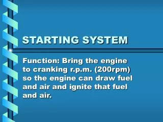
ELECTRICAL I LESSON 4 STARTING SYSTEM BASICS
The purpose of the starting system is to crank the engine at approximately 200rpm so enough compression is created that it will start.
Automotive Starter Motor Components • Field Magnets or Poles • The field magnets set up the stationary magnetic field. • The field is usually 4 electromagnets or 4-6 permanent magnets. • The poles are mounted inside the starter case (frame).
Armature • 16-10 gauge copper windings on a shaft that produce an electromagnetic field which reacts with the poles and rotates. • Winding types: • Wave - the ends of each winding (loop) are connected to commutator segments (bars) 90o or 180o apart. • Each bar has two loops’ ends connected to it. • This type is most common because it has low resistance. • Lap - the ends of each loop are connected to adjacent bars. • Each bar has two loops’ ends connected to it.
Commutator & brushes • The commutator is made up of copper bars insulated from each other. • The ends of the armature windings are connectedto the commutator segments. • The brushes allow for a rotating connection to the armature windings. • Automotive starters have two pairs of brushes; 2 positive (insulated) and 2 negative (ground or non-insulated).
Bushings & Bearings • Bronze self-lubricating bushings or sealed roller bearings are used to support the armature shaft and reduction gears.
Reduction Gears • Spur gears or a planetary gear set may be used to increase pinion drive gear torque while reducing its speed. • This allows a light weight motor to turn at high speed and draw less current. • Most permanent magnet motors use planetary gear reduction. • The reduction in speed is about 2:1 to 5:1.
INTERNAL MOTOR CIRCUITS • Starter motors with electromagnetic fields can be internally connected three possible ways:
Series - • The field coils and armature are in series with each other. • This offers high torque at start-up which drops off quickly as the motor speeds up.
Shunt - • The field coils are parallel to the armature. • This offers low torque at start-up which increases as the motor speeds up. • Not used in automotive starters.
Compound - • Some field coils are in series with the armature and some are parallel to it. • This offers good torque at start-up which stays adequate throughout the motor’s range of speed.
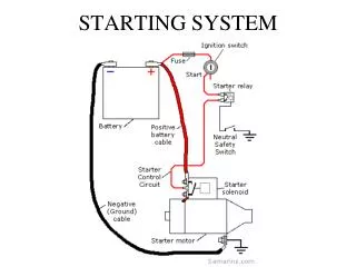
The starting system consists of two circuits: Motor and Control
Starter Motor Circuit • Controls the current from the battery to the motor. • It ranges from 100A to 250+A.
Components of the motor circuit: • Starter motor • Solenoid or Relay - high current switch contacts • Battery • Cables - 2 gauge to 6 gauge
Control Circuit • Controls the current from the battery to the solenoid or relay coil. • It ranges from 20A to 70A.
Components of the control circuit: • Ignition switch • Solenoid or Relay - electromagnetic coil • Battery • Neutral safety or Clutch switch - prevents cranking in gear • Starter motor - provides a ground for the solenoid’s pull-in winding.
The Starter Motor to Engine Connection • The motor armature has a drive gear (pinion) on the end of its shaft. • The drive pinion meshes with the ring gear on the flywheel or flexplate. • The gear ratio between the two is 15:1 to 20:1. • While the engine is off or running a spring pushes the pinion away from the ring gear.
There are three ways used to engage the pinion while the engine is being cranked.
Solenoid • The pinion is engaged by a shift fork lever moved by the solenoid plunger. • The solenoid has two coils. • The pull-in winding is energized to move the plunger against the spring and engage the drive pinion. • The pull-in winding is de-energized as soon as the pinion is engaged to reduce current draw on the battery. • The hold-in winding is energized to help engage the drive pinion. • It remains energized to hold the pinion while the engine is being cranked. • The solenoid also contains the high current switch contacts which close and turn the motor on when the plunger is pulled in.
Solenoid Type “A” initial crank current flow. • Click here for animation.
Solenoid Type “B” initial crank current flow. • Click here for animation.