Download
1 / 49
490 likes | 605 Views
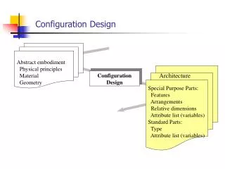
Configuration Design part 3. Engine Placement. ENGINE PLACEMENT. Factors to be considered: Effect of power changes or power failures on Stability & Control. Drag of the proposed configuration. Weight & Balance considerations.

E N D
Configuration Design part 3 Engine Placement
ENGINE PLACEMENT Factors to be considered: • Effect of power changes or power failures on Stability & Control. • Drag of the proposed configuration. • Weight & Balance considerations. • Inlet requirements and resulting effect on installed thrust and efficiency. • Accessibility and maintainability.
ENGINE PLACEMENT: Propeller-Driven AC • Option 1: Engines placed along fuselage centerline. Pros: • No thrust asymmetry in the event of engine failure. Cessna Skymaster • High thrust line. Dornier CD-2 Seastar • Important for amphibian ac.
ENGINE PLACEMENT: Propeller-Driven AC • Option 2: Engines placed symmetrically on the wing King Air Pros: • Most attractive aerodynamically & structurally. • Prop slipstream has favorable effect on stall (built-in safety against stall) • Prop slipstream increases L, especially when TE flaps are employed.
ENGINE PLACEMENT: Propeller-Driven AC • Option 2: Engines placed symmetrically on the wing Cons: • Engine failure may cause high windmilling D before prop is feathered. Induced YM and PM present control problems especially during TO. • Variation of engine power changes the downwash on the tail NB:If props are placed behind the wing, prop plane must be at least 0.5 c behind the TE to avoid vortex excitation from the flaps or the TE onto prop blades! (GP-166, B-36 : prop fatigue, broken blades)
ENGINE PLACEMENT: Propeller-Driven AC • Pusher vs. Tractor Pusher Pros: • Stabilizing tendency in both pitch and yaw when compared to tractors. This feature can result in reduced tail surface requirements. • Lower cabin interior noise.
ENGINE PLACEMENT: Jet AC Intake requirements: Must • Provide const. airflow at different engine settings and flight conditions. • Limit flow distortion and turbulence at the compressor face. • Have short length, otherwise increased W and p-loss. Must not • Change excessively the direction of the oncoming air at different aoa. • Allow the wake of a partially stalled wing to enter the inlet duct (i.e., wing LE is unsuitable for intake location) • Generate unstable flow in sideslipping (air oscillating instead of entering the duct; problem with split intakes). • Have pronounced curvature.
ENGINE PLACEMENT: Single Engine Jet ACengine mounted inside the fuselage Problem: Intake & exhaust duct location Solutions 1.1 Pitot Type Intake Fokker S-14, MIG-17 Pro: Provides the engine w. undisturbed flow for all flight conditions Con: Requires long inlet duct, which generally has to be divided at the level of the cockpit – low intake efficiency
ENGINE PLACEMENT: Single Engine Jet AC 1.2 Wing Root InletHawker Hunter Con: Difficult to meet the intake requirements (i.e., supply the engine with the required airflow at different intake velocities) and cope w. changes in aoa & aos. An additional constraint is that the local airfoil shape must not be modified excessively.
ENGINE PLACEMENT: Single Engine Jet AC 1.3 Side Inlets (Scoop Type)X-35 JSF Problems: • Additional D. To minimize this D, the airscoops must not be too short and must be well faired. • A divertor is needed to prevent the fuselage BL from entering the duct but this also increases D. • The inlet opening must be located far ahead of the wing to avoid interference and excessive variations in the intake conditions.
ENGINE PLACEMENT: Single Engine Jet AC 1.4 Top Inlets Miles Student, North American YF-107A Problem: The opening must be raised far above the fuselage to avoid BL and wake ingestion at large aoa.
ENGINE PLACEMENT: Single Engine Jet AC 1.5 Split Bottom Inlet North American Rockwell Buckeye Pro: Attractive for mid-wing and high-wing ac Con: Measures must be taken to avoid ingestion of debris during taxiing and TO.
ENGINE PLACEMENT: Single Engine Jet AC Exhaust requirements: Must • Be as short as possible; exhausts cause T-loss = 0.3% per ft-length or 1% per m-length. 2 tail-booms can be used for this purpose, offering the additional advantage of excellent engine accessibility. Must not • Not allow the hot jet efflux to impinge on the ac structure; for M<1 in parallel flow, the expanding gases form a cone with semi-apex angle = 6 deg.
ENGINE PLACEMENT: Single Engine Jet AC 1.6 Rear End ExhaustF-16 Pro: Keeps efflux away from the ac w/o any special precautions Cons: • Structural problems • Complicated fairings must be used around the exhaust
ENGINE PLACEMENT: Single Engine Jet AC 1.7 Split ExhaustHawker Sea Hawk Cons: • Structural problems • Complicated fairings must be used around the exhaust
ENGINE PLACEMENT: Multi Engine Jet AC 2.1 Engines buried entirely within the wing root De Havilland Comet, Avro Vulcan, Vickers Valiant, Handley Page Victor, Tupolev 104 Pros: • Low D. • Better maneuvering capabilities as a result of the low W/S (larger S) and low CL in cruise. Also, no compressibility problems such as buffeting. • Smaller nose-up pitching moment due to sweep angle because of the low AR. • Better low speed performance due to the low W/S. • Better from the aeroelastic point of view because the low R wing box structure offers greater stiffness. • If LFC is used (ex. BL suction), low T engines integrated inside the fuselage of the wing in combination with a low W/S may be used.
ENGINE PLACEMENT: Multi Engine Jet AC 2.1 Engines buried entirely within the wing root Cons: • Accessibility to the engines: Detachable skin panels are necessary at a location where the wing is highly stressed. • Safety: In the event of an engine fire the likelihood that the fire will spread to the fuel stored in the wing is great.
ENGINE PLACEMENT: Multi Engine Jet AC 2.2 Pod-Mounted Engines Pros: • Safety: in the event of an engine fire the likelihood that the fire will spread to the fuel is limited (main argument for the choice of the B-47 configuration) • Optimum engine operation due to short intake & exhaust ducts • Engine accessibility. • Current high bypass ratio engines together with the development of efficient HLS favor the use of high W/S (smaller S) and pod-mounted engines Con: Higher D penalty
ENGINE PLACEMENT: Multi Engine Jet AC 2.2.1 Pod-mounted engines suspended below the wing B-47, An-225, AB-380, B-777 Pros: • Structural advantages: the mass of the engines & pylons lead to a reduction in the root BM, thus lightening the wing structure. If engines are placed ahead of the wing flexural axis, they also constitute a mass balance against flutter. • Easy engine accessibility for maintenance. • Favorable aerodynamic effects of the pylons at large: • Tend to counteract the nose-up PM of swept back wings. • Act as fences, which are often used on “clean” wings.
ENGINE PLACEMENT: Multi Engine Jet AC 2.2.1 Pod-mounted engines suspended below the wing Cons: • Engines placed too far outboard increase LND impact. • Engines placed too far outboard require a large fin. • Higher D. • Large YM & PM in case of engine failure.
ENGINE PLACEMENT: Multi Engine Jet AC 2.2.2 Pod-mounted engines fitted to the rear of the fuselage Sud-Aviation Caravelle, DC-9 Pros: • “Clean” wing. • Low door level. • Little asymmetric T in case of engine failure. Cons: • Large c.g. travel w. variation in loading conditions. • Deep stall because of the T-tail. • W increase due to required local “beefup” of the structure. • Loss of useful space in fuselage tail; result = longer fuselage for same PL. • In general, OEW will be about 2% greater. • Engines are not easily accessible for maintenance. • At full PL large download on the tail; result = lower L/D.
ENGINE PLACEMENT: Multi Engine Jet AC 2.3 Mounting of a central engine 2.3.1 Engine buried in the fuselage B-727, L-1011 Cons: • Long and curved inlet; loss in intake efficiency. • Heavier.
ENGINE PLACEMENT: Multi Engine Jet AC 2.3.1 Engine pod-mounted on top of the fuselage Problem: Fin forms an obstruction. Solutions: • Cigar engine (DC-10) • Butterfly tail