Download
1 / 9
90 likes | 93 Views
Learn how to create a simple radiotransmission using a videorecorder and TV receiver. This guide explains the different connection methods and provides experiments you can try. Suitable for beginners.

E N D
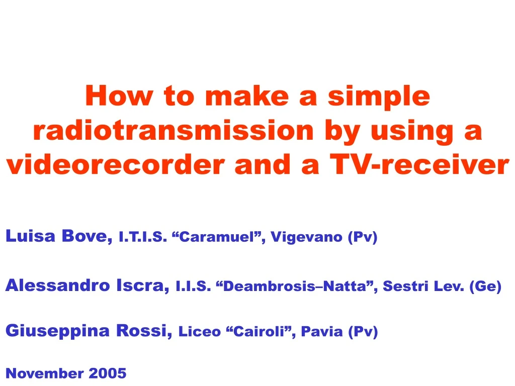
How to make a simple radiotransmission by using a videorecorder and a TV-receiver • Luisa Bove, I.T.I.S. “Caramuel”, Vigevano (Pv) • Alessandro Iscra, I.I.S. “Deambrosis–Natta”, Sestri Lev. (Ge) • Giuseppina Rossi, Liceo “Cairoli”, Pavia (Pv) • November 2005
The videorecorder and the TV-receiver • Tipically, a videorecorder can be connected to a TV-receiver in 3 different ways: • By using the SCART cable • By using audio/video cables or similars • Between the coaxial antenna cable. Female coax connector (from antenna) Typical rear side of a VCR Scart(s) Male coax connector (radiofrequency from VCR to TV) Power cable
The connection with the coaxial cable • When the connection is realized between the coaxial cable, the videorecorder emulates a TV transmitter and feeds the cable with a radiofrequency signal. Rear side of TV Coaxial cable
Let’s transmit via the coaxial cable • Let’s disconnect all cables from our videorecorder, with the only exception of the coaxial cable between the VCR and the TV-receiver (and, obviously, the power cable). • Let’s set up the VCR for playing a cassette. • Let’s tune the TV-receiver on the VCR transmitted channel. • Now the TV-receiver is receiving the VCR radiofrequency signal.
Let’s cut the cable • After creating or buying another very cheap coaxial cable, we may cut it and obtain (by stripping) two small dipole antennas. Now we can see that the TV-receiver receives with a wireless connection. Rear side of TV Suggested length: l/4
Some experiments • According to the very low power transmitted by the VCR, we can make: • - Several experiments on polarization; • Some experiments on transmissions through several objects; • Antennas with better performances.
A little problem • The received signal might be corrupted by a signal radiated by a near TV transmitter. • In this case it is necessary to tune first the TV receiver and then the VCR on a new RF channel (see your manuals).
Channels and frequencies • Videorecorders grenerate signals in the “Ultra High Frequency” band (UHF). Frequencies are related to a channel identifier N that varies between 21 and 69. • The frequency associated to the video signal is: • fV = 471.25 + (N – 21) × 8 MHz. • The frequency associated to the audio signal is: • fa = fV + 5.5 MHz.
Warnings • Since the VCR and the TV-receiver are supplied by 230 V, don’t touch antenna conductors. • Radiotransmissions are regulated by severe laws. Don’t connect amplifiers between the VCR and the transmitting antenna.