Download
1 / 66
670 likes | 724 Views
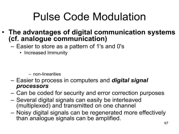
Pulse Modulation. Objectives To explain sampling theorem and analyze sampling process To study pulse amplitude modulation (PAM) To illustrate time division multiplexing (TDM) method To study pulse code modulation (PCM) To describe quantization process To determine quantization noise

E N D
Pulse Modulation • Objectives • To explain sampling theorem and analyze sampling process • To study pulse amplitude modulation (PAM) • To illustrate time division multiplexing (TDM) method • To study pulse code modulation (PCM) • To describe quantization process • To determine quantization noise • To describe encoding process • To determine transmission bandwidth • To study differential pulse code modulation (DPCM) • To study delta modulation (DM) • To compare PCM and DPCM, PCM and DM systems
Pulse Modulation In amplitude modulation and angle modulation, some parameter of sinusoidal carrier wave is varied continuously in accordance with the message signal. This is referred to as analog modulation.
Pulse Modulation If the carrier consists of (discrete) pulse trains, some parameter of the pulse train is varied in accordance with the message signal, it is called pulse modulation. After pulse modulation, the message signal becomes discrete. One of the major concern: How to recover the message signal from the discrete pulse trains?
Pulse Modulation Sampling Theorem A bandwidth limited signal having no frequency components higher than fm Hz may be completely recovered from its samples taken uniformly at a rate at least 2fm samples per second, i.e. the sampling frequency is fs = 2fm Hz. How to prove the sampling theorem? According to our knowledge, a pulse train is a periodic function. What is the spectrum of a pulse train?
Pulse Modulation Fourier transform of a periodic function A periodic function f(t), of period Ts, or angular frequency s, can be expressed in a Fourier series where Fn is the Fourier coefficient defined by
Pulse Modulation Since 1 2() from frequency shifting property, we have then for a periodic function its Fourier transform can be expressed as
Pulse Modulation In particular, if the periodic function is a set of impulse trains, its Fourier coefficient then becomes thus the Fourier transform of a set of impulse trains becomes
Pulse Modulation For a message signal g(t) whose spectrum is band- limited to fm Hz (or m = 2fm radian/s), in the sampling process, g(t) is multiplied by a set of impulse train, the product becomes
Pulse Modulation So the sampled signal is a product of message signal and a set of impulse trains According to the convolution theorem, the sampled signal Spectrum is where we used the properties g(t) (t) = g(t) and g(t) (t – T) = g(t – T) Proof
Pulse Modulation The signal spectrum G() can be recovered by the use of a low-pass filter if there is no overlap between the successive cycles of Gs(). This requires s 2m or fs 2fm or the sampling interval Ts 1 / 2fm Up to this point, we have proved the sampling theorem. *The minimum sampling rate 2fm is also called the Nyquist rate.
Pulse Modulation • What does sampling theorem tell us? • to convey the information contained in a band-limited signal it is necessary to send only a finite number of discrete samples. • a message signal that is band-limited to fm Hz is completely specified by its values at intervals spaced no greater than TS = 1/2fm seconds apart. • In pulse modulation, these discrete samples are used to vary a parameter of a pulse waveform.
Pulse Modulation Discrete samples play the role of message signal. Notice that these discrete samples are discrete in time but continuous in amplitude which means our pulse modulation is an analog pulse modulation. The pulse amplitude takes an analog value.
Pulse Modulation Analog pulse modulation • Pulse amplitude modulation (PAM) • Pulse width modulation (PWM) • Pulse position modulation (PPM).
Pulse Modulation Pulse amplitude modulation (PAM) The amplitude of a train of constant-width pulses is varied in proportion to the sample values of the message signal. In this scheme, the message is multiplied by a pulse train, which is similar to DSB-SC system.
Pulse Modulation Pulse amplitude modulation (PAM) The PAM signal spectrum is A distortion is introduced because of the shape of the sampling pulse so that the spectral density G() has lost its original shape. How to correct such a distortion?
Pulse Modulation A method of signal recovery is to use a filter that has a transfer function Equalization The technique of correcting the frequency response of a system for a known distortion is called equalization. Equalization is often used in correcting distortions which are known but over which one has little control.
Pulse Modulation The message is recoverable by lowpass filtering if fS > 2m, where m is the highest frequency component contained in the message. If fS < 2m, spectral overlap occurs and lowpass filtering can recover only a distorted form of the message. PAM signals can be multiplexed in the time domain.
Pulse Modulation Time division multiplexing (TDM) The transmission of several sampled signals at a time-sharing basis is called time division multiplexing (TDM). To recover the individual message at the receiver, it is necessary to sample in a synchronous manner to that done at the transmitter. Can analog signal be used in TDM?
Pulse Modulation It is quite easy to see that the minimum bandwidth for TDM transmission is proportional to the product of the message signal bandwidth and the number of the multiplexed signals. (This assumes that all signals have the same bandwidth.)
Pulse Modulation Comparison between FDM and TDM In TDM, multiple incoming signals are sliced into small time intervals, whereas in FDM the incoming signals are placed on different frequency ranges. Therefore, in the time domain, all the signals overlap in FDM, whereas signals may overlap in the frequency domain in TDM. This implies that an analog modulation system cannot use TDM unless sampling is performed (to changethe system into a pulse modulation system.)
Pulse Modulation Comparison between FDM and TDM In TDM, all the channels requireidentical circuits, thus providing an advantage in simplicity to TDM. In FDM, different carriers are generated for different channels. Also, different bandpass filters are required because each channel occupies a different frequency band. However, in TDM, sampling needs to be done at high speeds and synchronization of timing between the transmitter and the receiver must be achieved. This is a disadvantage.
Pulse Modulation PAM is still an analog pulse modulation. It isnot completely digital because the amplitudes of the pulses takes analog value. In analog pulse modulation, information is transmitted in analog form, but the transmission takes place at discrete times. If the message signal is represented in a form that is discrete in both time and amplitude, then we have digital pulse modulation. In digital pulse modulation, the signal transmission is in digital form, as a sequence of coded pulses.
Pulse Modulation In digital pulse modulation, PAM signals need to be further digitized and then encoded for transmission. This is achieved in a pulse code modulation (PCM) system. Binary PCM (where the pulses have only two permissible values) is the most common. We will confine our discussion to binary PCM system. How to produce a PCM signal?
Pulse Modulation A PCM signal is produced by an analog-to-digital conversion process.
Pulse Modulation Pulse code modulation (PCM) system Quantization Quantizationis the process of transforming the sampled amplitude of a message signal into a discrete level taken from a finite set of possible amplitudes.
Pulse Modulation How to perform the quantization? 1. The amplitudes of signal m(t) lie in the range(- mp, mp), which is partitioned into L intervals, each of magnitude = 2mp/L. 2. Each sample amplitude is approximated by the midpoint value of the interval in which the sample falls.
Pulse Modulation The amplitude range: (- mp, mp), [mp is not necessarily the peak amplitude of m(t)] Interval: = 2mp/L In quantization process, a sampling value is approximated by the midpoint of the interval. This introduces an error q(t), defined as the difference between the message signal m(t) and the corresponding quantized sample mq(t), q(t) = m(t) – mq(t) This error is called the quantization noise.
Pulse Modulation Quantization noise Since q(t) is uniformly distributed over the interval (-/2, /2), i.e., the error has equal probability to lie in the range (-/2, /2), the probability density is then 1/, hence the mean square value of q(t) is given by
Pulse Modulation Quantization noise power Since we can assume that the time average is equal to the statistical average, the quantization noise power is then the output signal-to-noise ratio is
Pulse Modulation From above discussion, it is clear that quantization results in a loss of information. (Information can also be lost in PAM due to noise) Such an information lost due to quantization may be reduced by increasing the number of levels used, L. e.g. 8 to 16 levels are sufficient for speech communication.
Example: The digital audio compact optical disc (CD) system uses 16 bit quantization and a sampling rate of 44.1 kHz per channel. Assuming the audio signal has a peak to mean power ratio of 13 dB, occupies the frequency band 0 to 20 kHz and that the recovery filter has an effective bandwidth, allowing for the finite cut-off rate of a practical filter of 22 kHz, estimate the signal to quantization noise ratio attainable. Solution: fs = 44.1 kHz, n = 16, thus we have L = 216 quantization levels. So we have
Pulse Modulation Encoding After sampling and quantization, the analog message signal becomes discrete in values, but it is still not in the form best suited for transmission. In order that the signal is best suited for transmission, i.e. more robust to noise and interference, an encodingprocess is required to translate the discrete samples to a more appropriate form, such as the binary digits.
Pulse Modulation Encoding
Pulse Modulation Encoding
Pulse Modulation • Transmission bandwidth • Digital signals use much more bandwidth than analog signals. This can be explained as follows: • The binary digits must be transmitted in the sampling interval originally allotted to one sample, the binary pulse widths are correspondingly narrower and therefore • occupy a larger bandwidth according to the inverse time–bandwidth relationship. • The transmission bandwidth increases proportionately to the number of binary pulses needed.
Pulse Modulation Transmission bandwidth For a binary PCM, a distinct group of binary digits (bits) is assigned to each of the L quantization levels. As n binary digits can be arranged in 2n distinct patterns, L 2n or n log2L Each quantized sample is thus encoded into n bits.
Pulse Modulation Transmission bandwidth According to sampling theorem, a signal m(t) band-limited to B Hz requires a minimum of 2B samples per second, a total of 2nB bits per second (bps) is required, that is, 2nB piece of information per second. Because a unit bandwidth (1 Hz) can transmit a maximum of two pieces of information (1 or 0) per second, a minimum channel bandwidth is given by BT = nB Hz This is the theoretical minimum transmission bandwidth required to transmit the PCM signal.
Pulse Modulation Bandwidth – Signal-to-noise ratio trade-off Assuming that L = 2n, the output signal-to-noise ratio can be expressed as where since n = BT/B, we have It shows that the signal-to-noise ratio increases exponentially with the transmission bandwidth BT.
Pulse Modulation If n increases, then BT = nB also increases, this leads to that the signal-to-noise ratio increases. In other words, a larger channel bandwidth corresponds to a higher signal-to-noise ratio. If you want to improve the signal-to-noise ratio, you have to use a larger channel bandwidth. --- There is a trade-off between the SNR and the channel bandwidth.
Pulse Modulation Demodulation of PCM signal When the PCM signal is demodulated, the signal-to- noise ratio obtained at the receiver should be identical to that at the transmitter. Any noise which may be added during transmission can be eliminated because the binary signal can have only two known values, 1 and 0. If the value of the pulse is different from the set values, we know that it is due to external noise and we can readjust it to its original value.
Pulse Modulation Key advantage of PCM In analog system, a message signal suffers the channel noise and the signal distortion, which are cumulative. Amplification is of little help because it enhances the signal and the noise in the same proportion. The analog signal can not cleaned periodically, and thus the transmission is not reliable. In PCM system, the new, clean signals can be completely regenerated at repeater stations because all the information is contained in the code. The PCM signal can then be transmitted over long distance with great reliability.
Pulse Modulation Other advantages of PCM and digital communications 1. Allow us to use computer as a tool for communications. (Computers generate digital signals.) 2. Digital communications systems use a type of coding (error correction code) which can minimize noise and interference, thus producing high quality signals. 3. Digital systems can use both types of multiplexing (FDM and TDM) so that many different sources of information can be handled efficiently.
Pulse Modulation 4. Transmission media (such as optical fibres) that have wide bandwidths are available so we can cope with the large bandwidth requirements of digital systems. 5. Digital signal processing has become well established. Digital electronic circuits are now easy to design and to implement in integrated circuit (IC) form.
Pulse Modulation • Disdvantages of digital communications: • Requires wider bandwidths than analog transmission • Requires synchronization between receiver and transmitter.
Pulse Modulation Minimum Information Capacity (Bit Rate) of PCM Systems The information capacity is defined as the number of bits that can be transmitted per second (bit rate). Since we are using the Nyquist rate for sampling, the minimum bit rate transmitted for a binary system is That is, the minimum bit rate is equal to double the product of the signal bandwidth and the number of binary pulses.
Pulse Modulation Example: Plain-old-telephone system (POTS) Voice bandwidth limited to: 3.4 kHz Babdwidth including guard band: 4 kHz Sampling frequency: 8 kHz Sampling rate: 8,000 samples/s Coding: binary 8 bits per sample (L = 28 = 256 quantization levels) Bit rate :