Download
1 / 13
330 likes | 701 Views
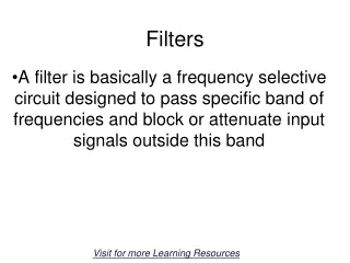
Passive Filters. All materials are taken from “Fundamentals of electric circuits”. Introduction. A filter is a circuit that is designed to pass signals with desired frequencies and reject or attenuate others.

E N D
Passive Filters All materials are taken from “Fundamentals of electric circuits”
Introduction • A filter is a circuit that is designed to pass signals with desired frequencies and reject or attenuate others. • A filter is a passive filter if it consists of only passive elements R,L, and C. • It is said to be an active filter if it consists of active elements (such as transistors and op amps) in addition to passive elements R, L,and C.
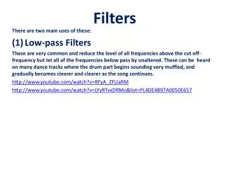
There are four types of filters whether passive or active: • A lowpass filter passes low frequencies and stops high frequencies, • A highpass filter passes high frequencies and rejects low frequencies • A bandpass filter passes frequencies within a frequency band and blocks or attenuates frequencies outside the band • A bandstop filter passes frequencies outside a frequency band and blocks or attenuates frequencies within the band
Transfer Function • The frequency response of a circuit is the variation in its behavior with change in signal frequency. • The transfer function H( ) of a circuit is the frequency-dependent ratio of a phasor output Y() (an element voltage or current) to a phasor input X() (source voltage or current).
The transfer function can be expressed in terms of its numerator polynomial and denominator polynomial as • A zero, as a root of the numerator polynomial, is a value that results in a zero value of the function. • A pole, as a root of the denominator polynomial, is a value for which the function is infinite.
The Decibel Scale For the case when R2 = R1
Bode Plots • The frequency range required in frequency response is often so wide that it is inconvenient to use a linear scale for the frequency axis. • Bode plots are semilog plots of the magnitude (in decibels) and phase (in degrees) of a transfer function versus frequency.
Lowpass Filter • A typical lowpass filter is formed when the output of an RC circuit is taken off the capacitor A lowpass filter can also be formed when the output of an RL circuit is taken off the resistor
Highpass Filter • A highpass filter is formed when the output of an RC circuit is taken off the resistor. • A highpass filter is designed to pass all frequencies above its cutoff frequency c. • A highpass filter can also be formed when the output of an RL circuit is taken off the inductor.