Download

1 / 52
530 likes | 1.04k Views
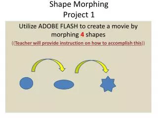
Project Image Morphing. Presented By. Sharmila Gupta. Digital Image Manipulation. Simple pixel Modification. Interpolation/ Extrapolation. Compositing. Convolution. Dithering. Warping. Morphing. Simple Pixel Modification. Applying same degree of change in every pixel.

E N D
Project Image Morphing Presented By Sharmila Gupta
Digital Image Manipulation Simple pixel Modification Interpolation/ Extrapolation Compositing Convolution Dithering Warping Morphing
Simple Pixel Modification Applying same degree of change in every pixel Convert to Gray f(r,g,b) = .3r + .52g + 10b Threshold if v > threshold then f(v) = 1 else f(v) = 0 Invert f(v) = 1-v Brighten/darken f(v) = ßv for ß >= 0
Image Interpolation/Extrapolation Offers a general, unifying approach to many common point and area image processing operations. Brightness, contrast, saturation, tint, and sharpness can all be controlled with one formula, separately or simultaneously. Change Contrast Original More Contrast Less Contrast Change Saturation Original More Saturated Less Saturated
median filtered image Image with “impulse” noise Image Interpolation/Extrapolation Brighten/darken Original More Bright Less Bright Noise removal
Compositing Compisiting images involves combining separate image layers into one Layers may be moved and arranged. Composite Original
Convolution Used for different image processing, removing blur-ness, defining edge, restore special effect by filtering, masking or other technique. Edge Enhancement Original Edge Defined Blur-ness Blurred De-blurred
Dithering Monitors and image files limited to 256 colors can create the illusion of more colors by Dithering the available colors in a scattered pattern, approximating the desired color. Image editors often use dithering to convert true color images to indexed color images. True-color Image Dithered Image
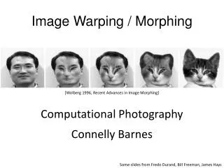
Image Morphing It comes from the word Metamorphosis Metamorphosis: Change shape, size, form or appearance
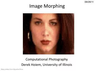
What is Image Morphing ? Morphing can be defined as: Transition from one object to another Process of transforming one image into another. An animation technique that allows you to blend two still images, creating a sequence of in – between pictures that when played in Quick Time, metamorphoses the first image into the second.
What is Image Morphing ?contd.. A process of transforming two images where it seems like the first melts, dissolves and re-arranges itself to become the second one
General View It is broadly two-step process: First image is gradually distorted and is faded out The second image starts out totally distorted toward the first and is faded in.
Classification of Morphing Morphing classified into three types Image-based Method Volume-based approaches Boundary representations (B-rep) -based approaches
Image-based Morphing Two steps are: Warping two images to make them having the same shape Cross dissolving the resulting images
Image-based Morphing WARPING ?
Image-Based Morphing - Warping A warp is a 2-D geometric transformation and generates a distorted image when it is applied to an image Warping an image means apply a given deformation to it Two ways to warp an image: Forward Mapping Reverse Mapping
Forward Mapping Each pixel in the source image is mapped to an appropriate pixel in the destination image. Source Image Destination Image Some pixels in the destination image may not be mapped Source Image Destination Image
Reverse Mapping This method goes through each pixel in the destination image and samples an appropriate source image pixel All destination image pixels are mapped to some source image pixel. This mapping used in the Beier/Neely line morphing method.
Cross Dissolving A cross-dissolve is a sequence of images which implements a gradual fade from one to the other. Very primitive No smooth transition
Image-based Morphing - Example Source Image Destination Image Do Morphing
Image-based Morphing - Example Baby to Grandpa Morphing Groom to Bride Compositing Warping
Image-Based Morphing - Other option ! Better option than Cross - Dissolving: Field/Line Morphing Mesh Mapping Multilevel Free-form Deformation (MFFD)
Field/Line Morphing What pixel coordinate in the source image do we sample for each pixel in destination image ? Correspondence achieved using feature line(s) in source and destination images Source Image Destination Image
Field/Line Morphing Two step process Step I : Interpolating the lines: Interpolate the coordinates of the end points of every pair of lines. Step II : Warping the Images:Each of the source images has to be deformed towards the needed frame.The deformation works pixel by pixel is based on the reverse mapping. This algorithm is called Beier-Neely Algorithm.
BEIER-NEELY ALGORITHM Divide the two image to be morphed into lines
BEIER-NEELY ALGORITHM (contd.) Create Intermediate Morph for both images Intermediate Morph ? Use corresponding lines in both the images to redefine a new position for each pixel according to a parameter t If t = 0 for First image and t = 1 for Second Image then Intermediate Morph: 0<t<1
BEIER-NEELY ALGORITHM (contd.) Compute line endpoints in the intermediate morph A = endpoint of a line in First image B = endpoint of a line in Second image AB = endpoint of the line in Intermediate image = (1-t)*A+t*B Use Field Morphing to warp First Image according to intermediate line endpoints Use Field Morphing to warp Second Image according to intermediate line endpoints Cross-Dissolve the warped images using t to define weighted pixel average
BEIER-NEELY ALGORITHM (contd.) Cross Dissolve the intermediate warped images Warped First Image Warped Second Image
BEIER-NEELY ALGORITHM - PIXEL POSITION Compute position of pixel X in destination image relative to the line drawn in destination image.(x,y) (u,v) Q’ Q X v u P’ P Source Image Destination Image
BEIER-NEELY ALGORITHM - PIXEL POSITION Compute coordinates of pixel in source image whose position relative to the line drawn in source image is (u,v). (u,v) (x’,y’) Q’ Q X v v u u P’ P Source Image Destination Image
BEIER-NEELY ALGORITHM - PIXEL POSITION Computation of pixel X with respect to Line (x,y) (u,v) Q (qx,qy) (x-px)(qx-px)+(y-py)(qy-py) X (x,y) v (X-P).(Q-P) (qx-px)+(qy-py) ||(Q-P)||2 u (X-P).Perpendicular(Q-P) ||(Q-P)|| P (px,py) Destination Image (qy-py, -qx+px)
BEIER-NEELY ALGORITHM-WEIGHTED AVG. Computation of weighted pixel average Q (qx,qy) b lengthp X (x,y) Weight = a + dist v length = (qx-px)2 + (qy-py)2 dist = abs(v) if o<u<1 or dist = distance of (x,y) from P if u < 0 or dist = distance of (x,y) from Q if u > 1 u P (px,py) (a,b) controls influence of line for points near it
BEIER-NEELY ALGORITHM For each pixel X=(x,y) in the destination image DSUM=(0,0) , weightsum=0 for each line(Pi, Qi) calculate(ui,vi) based on Pi, Qi calculate (xi’, yi’) based on u,v and Pi, Qi calculate displacement Di = Xi’ – X for this line compute weight for line(Pi,Qi) DSUM+=Di*weight weightsum+=weight (x’y’) = (x,y)+DSUM/weightsum color at destination pixel(x,y) = color at source pixel(x’y’)
Mesh Morphing • Mesh is a rough presentation of an object • How it is done ? Meshed Image • Source and Destination images are meshed • Meshes for both images are interpolated • Intermediate images are cross-dissolved
Mesh Morphing-Algorithm • for each frame f do • Linearly interpolate mesh M, between Ms and Mt • warp Images to I1, using meshes Ms and M • warp Imaget to I2, using meshes Mt and M • Linearly interpolate image I1 and I2 • end
Mesh Morphing - Pros and Cons • Pros All control points affects the warping equally. • Cons Hard to fit the mesh in the image Not enough control on certain points when needed. A Mesh A Rendered Image
Multilevel Free Form Deformation (MFFD) Morphing two sequences of live action, rather than just two still images Mark all features in key frames Interpolate the features between key frames Do image metamorphosis on set of image pairs
Volume Based Approaches • Technique: The objects are expressed as level sets of distance functions Two steps: Warp: deform the 3D space in order to make the two objects to be morphed coincide as much as possible Interpolation: linear interpolate distance fields deformed by the warp • Interaction: The user interface allows to select feature (or anchor) points in each voxelized object space and map the anchor points of the source object to the anchor points of the target object
Volume Based Approaches D. Cohen-Or, D. Levin, A. Solomovoci. Three-dimensional distance field metamorphosis. ACM Trans. Graphics 17:116-141, 1998 http://www.math.tau.ac.il/~levin/
B-Rep Based Approaches Polyhedral Morphing using Feature based surface decomposition The users only need to specify a few corresponding pairs of features on the two polyhedra. They can then specify the trajectories along which these features travel during the morph using Bezier curves, as shown in the next page. The algorithm not only provides the user with high-level control in terms of specifying the features and trajectories, it also allows for local refinement
B-Rep Based Approaches Destination Image Source Image
B-Rep Based Approaches A. Gregory, A. State, M. C. Lin, D. Manocha, and M. A. Livingston. Interactive surface decomposition for polyhedral morphing. The Visual Computer (1999) 15:453-470 http://www.cs.unc.edu/~geom/3Dmorphing/