Download
1 / 29
310 likes | 834 Views
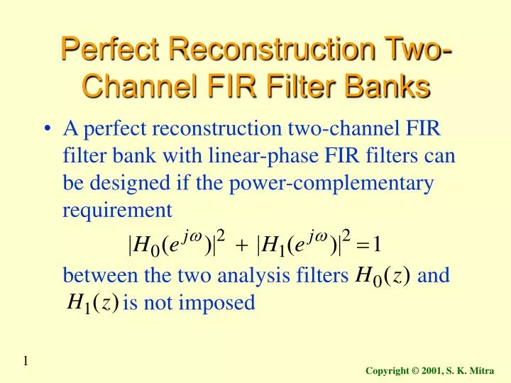
Perfect Reconstruction Two-Channel FIR Filter Banks. A perfect reconstruction two-channel FIR filter bank with linear-phase FIR filters can be designed if the power-complementary requirement between the two analysis filters and is not imposed.

E N D
Perfect Reconstruction Two-Channel FIR Filter Banks • A perfect reconstruction two-channel FIR filter bank with linear-phase FIR filters can be designed if the power-complementary requirement between the two analysis filters and is not imposed Copyright © 2001, S. K. Mitra
Perfect Reconstruction Two-Channel FIR Filter Banks • To develop the pertinent design equations we observe that the input-output relation of the 2-channel QMF bank can be expressed in matrix form as Copyright © 2001, S. K. Mitra
Perfect Reconstruction Two-Channel FIR Filter Banks • From the previous equation we obtain • Combining the two matrix equations we get Copyright © 2001, S. K. Mitra
Perfect Reconstruction Two-Channel FIR Filter Banks where are called themodulation matrices Copyright © 2001, S. K. Mitra
Perfect Reconstruction Two-Channel FIR Filter Banks • Now for perfect reconstruction we must have and correspondingly • Substituting these relations in the equation we observe that the PR condition is satisfied if Copyright © 2001, S. K. Mitra
Perfect Reconstruction Two-Channel FIR Filter Banks • Thus, knowing the analysis filters and , the synthesis filters and are determined from • After some algebra we arrive at Copyright © 2001, S. K. Mitra
Perfect Reconstruction Two-Channel FIR Filter Banks where and is an odd positive integer Copyright © 2001, S. K. Mitra
Perfect Reconstruction Two-Channel FIR Filter Banks • For FIR analysis filters and , the synthesis filters and will also be FIR filters if wherecis a real number andkis a positive integer • In this case Copyright © 2001, S. K. Mitra
Orthogonal Filter Banks • Let be an FIR filter of odd orderNsatisfying the power-symmetric condition • Choose • Then Copyright © 2001, S. K. Mitra
Orthogonal Filter Banks • Comparing the last equation with we observe that andk = N • Using in with we get Copyright © 2001, S. K. Mitra
Orthogonal Filter Banks • Note:If is a causal FIR filter, the other three filters are also causal FIR filters • Moreover, • Thus, for a real coefficient transfer function if is a lowpass filter, then is a highpass filter • In addition, Copyright © 2001, S. K. Mitra
Orthogonal Filter Banks • A perfect reconstruction power-symmetric filter bank is also called anorthogonal filter bank • The filter design problem reduces to the design of a power-symmetric lowpass filter • To this end, we can design a an even-order whose spectral factorization yields Copyright © 2001, S. K. Mitra
Orthogonal Filter Banks • Now, the power-symmetric condition implies thatF(z) be a zero-phase half-band lowpass filter with a non-negative frequency response • Such a half-band filter can be obtained by adding a constant term K to a zero-phase half-band filter Q(z) such that Copyright © 2001, S. K. Mitra
Orthogonal Filter Banks • Summarizing, the steps for the design of a real-coefficient power-symmetric lowpass filter are: • (1)Design a zero-phase real-coefficient FIR half-band lowpass filterQ(z) of order 2NwithNan odd positive integer: Copyright © 2001, S. K. Mitra
Orthogonal Filter Banks • (2) Letddenote the peak stopband ripple of • DefineF(z) = Q(z) + dwhich guaranteesthat for allw • Note:Ifq[n] denotes the impulse responseofQ(z),then the impulse responsef [n] ofF(z) is given by • (3) Determine the spectral factor ofF(z) Copyright © 2001, S. K. Mitra
Orthogonal Filter Banks • Example -Consider the FIR filter whereR(z) is a polynomial in of degreewithNodd • F(z) can be made a half-band filter bychoosingR(z) appropriately • This class of half-band filters has been called thebinomialormaxflat filter Copyright © 2001, S. K. Mitra
Orthogonal Filter Banks • The filterF(z) has a frequency response that is maximally flat atw = 0 and atw = p • ForN = 3, resulting in which is seen to be a symmetric polynomial with 4 zeros located at , a zero at , and a zero at Copyright © 2001, S. K. Mitra
Orthogonal Filter Banks • The minimum-phase spectral factor is therefore the lowpass analysis filter • The corresponding highpass filter is given by Copyright © 2001, S. K. Mitra
Orthogonal Filter Banks • The two synthesis filters are given by • Magnitude responses of the two analysis filters are shown on the next slide Copyright © 2001, S. K. Mitra
Orthogonal Filter Banks • Comments:(1) The order ofF(z) is of theform 4K+2,whereKis a positive integer • Order of isN = 2K+1,which is odd as required Copyright © 2001, S. K. Mitra
Orthogonal Filter Banks • (2)Zeros ofF(z) appear with mirror-image symmetry in thez-plane with the zeros on the unit circle being of evenmultiplicity • Any appropriate half of these zeros can be grouped to form the spectral factor • For example, a minimum-phase can be formed by grouping all the zeros inside the unit circle along with half of the zeros on the unit circle Copyright © 2001, S. K. Mitra
Orthogonal Filter Banks • Likewise, a maximum-phase can be formed by grouping all the zeros outside the unit circle along with half of the zeros on the unit circle • However, it is not possible to form a spectral factor with linear phase • (3)The stopband edge frequency is the same for F(z) and Copyright © 2001, S. K. Mitra
Orthogonal Filter Banks • (4)If the desired minimum stopband attenuation of is dB, then the minimum stopband attenuation ofF(z) is dB • Example -Design a lowpass real-coefficient power-symmetric filter with the following specifications: , and dB Copyright © 2001, S. K. Mitra
Orthogonal Filter Banks • The specifications of the corresponding zero-phase half-band filterF(z) are therefore: and dB • The desired stopband ripple is thus which is also the passband ripple • The passband edge is at • Using the functionremezordwe firstestimate the order ofF(z) and then using thefunctionremezdesignQ(z) Copyright © 2001, S. K. Mitra
Orthogonal Filter Banks • The order ofF(z) is found to be 14 implyingthat the order of is 7 which is odd as desired • To determine the coefficients ofF(z) we adderr(the maximum stopband ripple) to thecentral coefficientq[7] • Next, using the functionrootswe determinethe roots ofF(z) which should theretically exhibit mirror-image symmetry with double roots on the unit circle Copyright © 2001, S. K. Mitra
Orthogonal Filter Banks • However, the algorithm s numerically quite sensitive and it is found that a slightly larger value thanerrshould be added to ensuredouble zeros ofF(z) on the unit circle • Choosing the roots inside the unit circle along with one set of unit circle roots we get the minimum-phase spectral factor Copyright © 2001, S. K. Mitra
Orthogonal Filter Banks • The zero locations ofF(z) and are shown below Copyright © 2001, S. K. Mitra
Orthogonal Filter Banks • The gain responses of the two analysis filters are shown below Copyright © 2001, S. K. Mitra
Orthogonal Filter Banks • Separate realizations of the two filters and would require 2(N+1) multipliers and 2Ntwo-input adders • However, a computationally efficient realization requiringN+1 multipliers and 2Ntwo-input adders can be developed by exploiting the relation Copyright © 2001, S. K. Mitra