Download
1 / 22
330 likes | 904 Views
Atom interferometry. 11.1 Yang ’ s double-slit experiment 11.2 A diffraction grating for atoms 11.3 The three-grating interferometer 11.4 Measurement of rotation 11.5 The diffraction of atoms by light 11.6 Conclusions. background.

E N D
Atom interferometry • 11.1 Yang’s double-slit experiment • 11.2 A diffraction grating for atoms • 11.3 The three-grating interferometer • 11.4 Measurement of rotation • 11.5 The diffraction of atoms by light • 11.6 Conclusions
background The possibility of interferometry with atoms follows directly from wave-particle duality. This chapter explains how such matter waves have been used in interferometers that measure rotation and gravitational acceleration to a precision comparable with the best optical instruments. As in many important developments in physics, atom interferometry relies on simple principles-the first part of this chapter uses only elementary optics and the de Broglie relation
Detector s 11.1 Yang’s double-silt experiment This picture shows a typical experiment layout. Waves propagate from the source slit S through the two slits,1 and 2 , to a point P in the detection plane. The amplitude of the light at any point on the detection plane equals the sum of the electric field amplitudes that arrive at that point via slits 1 and 2, Slits of the same size contribute equally to the total amplitude at a point on the plane P:
The difference in the distance from to P and from to P is , where d is the slit separation. The angle and the distance X in the detection plane are related by . The transverse distances are drawn greatly exggerated for clarity; for the typical conditions given in the text the fringes have an angular separation of rad.
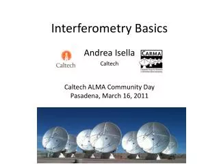
Grating Detector Supersonic beam of atoms and molecules (a) source Fig.11.2 (a) Diffractlon of a collimated atomic beam by a grating. To observe the source slit must be sufficiently narrow to make the matter waves coherent across several of the slits in the grating. carrier gas
(b) (c) 0 1000 500 -1000 -500 500 -1000 -500 0 1000 Detector position(um) Detector position(um) Fig 11.2 (b) The diffraction of a collimated beam of sodium atoms and molecules by the grating. (c) The diffraction pattern for a beam that contains only molecules .
The intensity is proportional to the square of this amplitude, Here is the phase difference between the two arms and is the maximum intensity. Bright fringes occur at positions in the detection plane where the contributions from the two paths interfere constructively; these correspond to ,with n an integer, or equivalently To find the spacing of the fringes in the plane of observation we define the coordinate X measured perpendicular to the long axis of the slits in the plane P . In terms of the small angle defined in Fig.11.1(b) this becomes
Here is the path difference before the slits . The path lengthdifference from the two slits of separationto P is . The last three equations give the spacing of the fringes as For an experiment with visible light of wavelength , slits of separation L=1m, The treatment so far assumes a small source slit at S that acts like a point source to illuminate the double slits coherently. The condition for this is that the double slits fall within the angular spread of the light diffracted from the source slit (Brooker 2003).The diffraction from a slit of width has an angular spreadof Therefore coherent illumination of two slits at a distance from this source slit requires ,or
11.2 A diffraction grating for atoms Figure 11.2 shows a apparatus with a highly-collimated atom beam of sodium incident upon a transmission grating. The experiments used a Remarkable grating with slits only 50 nm wide, spaced 100nm apart-equal widths of the bars and the gaps between them. Etching these very thin bar and their delicate support structure represents the state of the art in nano-fabrication. Figure 11.2(b) shows the diffraction pattern obtained with a mixture of sodium atoms and molecules, and Fig.11.2(c) shows the dlffraction of a beam of sodium molecules.
11.3 The three-grating interferometer Figure 11.3 shows an arrangement of three diffraction gratings a distance apart. This arrangement closely resembles a Mach-Zehnder interferometer for light, with a smaller angle between the two arms because of the achievable grating spacing. For two-beam interference the signal has the same form as eqn 11.3. In these interferometers the sum of the fluxes of the atoms, or light, in the two possible output directions equals a constant,i.e. when a certain phase difference between the arms of the interferometer gives destructive interference at the detector then the flux in the other output direction has a maximum.
Flg.11.3(a) An interferometer formed by three diffraction gratings spaced by a distance along the atomic beam, A collimated beam of atoms is produced, as shown in Fig.11.2. Wave diffraction at the first grating Gl split again at G2, so that some of the paths meet at G3. only the 0 and 1 diffraction orders are shown and to further simplify the diagram some of the possible paths between G2 and G3 have not been drawn completely.
11.4 Measurement of rotation Mach-Zehnder interferometer for matter waves shown in Fig.11.3 measures rotation precisely, as explained in this section. To calculate the phase shift cause by rotation in simple way we represent the interferometer as a circular loop of radius R, as in Fig.11.4. The wave traveling at speed v from the point S takes a time t=R/v to propagate around either arm of the interferometer to the point P diametrically opposite S. During this time the system rotates through an angle where is the angular frequency of rotation about an axis perpendicular to the plane of the interferometer. Thus the wave going one way round the loop has to travel l=2 Rt further than the wave in the other arm of the interferometer.
(c) A Mach-Zehnder interferometer for light-the optical system equivalent to the three-grating interferometer. The incident Wave hits beam splitter BSI and the reflected and transmitted amplitudes reflect off mirrors M1 and M2, respectively, so that their paths meet again at BS2. Interference between the two paths leads to a detected intensity (cf. eqn 11.3). The phase that arise from path length differences and phase shifts on reflection at the mirrors is assume to be fixed and represents the extra phase that is measured;
This corresponds to extra wavelengths, or a phase shift of The loop has area , so that A more rigorous derivation, by integration around a closed path, shows that this equation applies for an arbitrary shape, e.g. the square interferometer of Fig.11.3 (c). Comparison of this phase shift for matter waves of velocity v with that for light ,for an interferometer of the same area A, shows that The ratio equals the rest mass of the atom divided by the energy of each photon and has a value of ~ for Sodium atoms and visible light. This huge ratio suggest that
Fig.11.4 (a) A simplified diagram of an interferometer where the waves propagate from S to P. (b) Rotation at angular frequency about an axis perpendicular to the plane of the interferometer makes one path longer and the other shorter by the same amount, where t is the time taken for a wave to travel from S to P. This leads to the phase shift in eqn 11.10.
matter-wave interferometers have a great advantage, but at the present time they only achieved comparable results to conventional interferometers with light. Conventional interferometers with light make up the ground by: having much larger areas, i. e. a distance between the arms of metres instead of a fraction of a millimeter achieved for matter waves; the light goes around the loop many times; lasers give a much higher flux than the flux of atoms in a typical atomic beam. For example, in the scheme shown in Fig. 11.2 only a small fraction of the atoms emitted from the source end up in the highly-collimated atomic beam; as a source of matter waves the atomic oven is analogous to an incandescent tungsten light bulb rather than a laser.
11.5 The diffraction of atoms by light A standing wave of light diffracts matter waves, as illustrated in Fig . 11.5. This corresponds to a role reversal as compared to optics in which matter, in the form of a conventional grating, diffracts light. The interaction of atoms with a standing wave leads to a periodic modulation of the atomic energy levels by an amount proportional to the intensity of the light as explained in Section 9.6. The light of the atomic energy levels in the standing wave introduces a phase modulation of the matter waves. An atomic wavepacket (x,z,t) becomes (x,z,t) ei(x) immediately after passing through the standing wave; it is assumed that (x,z,t) changes smoothly over a length scale much greater than /2. This phase modulation has a spatial period of /2, where is the wave-length of the light not the matter waves.
Fig. 11.5 The diffraction of atoms by a standing wave light field. The angle of the first order of diffraction is related to the grating period d by sin=dB.
Fig.11.6 A Raman transition with two laser beams of frequencies and that propagate in opposite directions. Equation 11.13 gives the resonance condition, ignoring the effects of the atom’s motion (Doppler shift). The Raman process couples and so that an atom in a Raman interferometer has a wavefunction of the form (usually with either B=0 or A=0 initially).
11.6 conclusions 1) Matter-wave interferometers for atoms are a modern use of the old idea of wave-particle duality and in recent years these devices have achieved a precision comparable to the best optical instruments for measuring rotation and gravitational acceleration. 2) We have seen examples of experiments that are direct analogues of those carried out with light, and also the Raman technique for manipulating the momentum of atoms through their interaction with laser light, as in laser cooling.
3) Laser cooling of the atom’s longitudinal velocity, however, only gives an advantage in certain cases. Similarly, the high-coherence beams, or atom lasers, made from Bose condensates do not necessarily improve matter-wave devices-in contrast to the almost universal use of lasers in optical interferometers. 4) The interaction of atoms with the periodic potential produced by a standing wave gives a lot of interesting physics, in addition to the diffraction described here, and we have only scratched the surface of atom optics.