Download
1 / 14
140 likes | 254 Views
Electron Cloud Simulations Using ORBIT Code - Cold Proton Bunch model. April 11, 2007 ECLOUD07 Yoichi Sato, Nishina Center, RIKEN. Y. Sato ECLOUD07. 1. Outline ECloud Properties to Cold Proton Bunch in ORBIT.

E N D
Electron Cloud Simulations Using ORBIT Code- Cold Proton Bunch model April 11, 2007 ECLOUD07 Yoichi Sato, Nishina Center, RIKEN Y. Sato ECLOUD07 1
Outline ECloud Properties to Cold Proton Bunch in ORBIT • Proton Bunch Slope Dependence of ECloud Growth and Energy Distribution of Electrons Hitting Surface (triangular longitudinal line density profiles) Proton bunches of same head triangles and the effect of bunch slope Proton bunches of same tail triangles and the effect of primary electron amount • Prompt-Swept Electron Simulation and Discussion of Physics Parameters with Comparing PSR Data Constant proton loss rate to beam intensity Assumption of proton loss rate function of beam intensity • ECloud Recovery Simulation After Swept Proton loss rate estimation Inconsistency between the recovery estimation and prompt-swept slope fit • Conclusions Y. Sato ECLOUD07 2
PBunch Triangular Profiles 120ns PB tail 110ns PB tail 100ns PB tail 90ns PB tail Energy band 250eV-300eV corresponds to SEY peak • The longer tail of pBunch causes the larger eCloud and its higher growth rate. The steeper tail pBunch gives the higher energy of hitting electrons (E_0 > 250eV) and the lower SEY that may lead the lower growth rate. The energy distribution of surface hitting electrons of off-peak-band reduces ECloud growth Y. Sato ECLOUD07 3
PBunch Triangular Profiles • The carry-over and primary electrons before the peak of pBunch slightly change eCloud peak and growth rate. However, the slight differences imply that the pBunch effect to drive electrons may be mitigated by the existence of inside electrons during the beginning of pBunch tail slope. • To have long head in pBunch profile is a possible way to accumulate more protons in a bunch. And effect of carry over electrons surviving beam gap Effect of primary electrons stored in the head of proton bunch Y. Sato ECLOUD07 4
Future Study for Artificial PBunch • Comparison of ep instability between Long head profile (short gap) and isosceles triangular profile (large gap) using ORBIT capability of simulating proton bunch dynamics. Even a short gap can remove the ep oscillation of carry-over eCloud in front of the next bunch. • Simulation of ECloud development to proton bunches of triangular + saw profile. We can expect to mitigate trailing edge multipaction. The saw ratio and frequency should be optimized. Certainly, the biggest problem: how to realize them, is remaining. Y. Sato ECLOUD07 5
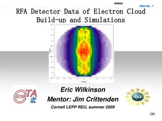
Prompt-Swept Electron Data from Electron Sweeper at PSR Beam Pulse HV pulse Swept electron signal Electron Signal (prompt electron) • The prompt electrons come out at the tail of the beam pulse. The Electron Sweeper (ES) functions as a large area Electron Detector (ED) until the HV pulse arrives. • The swept electron signal is narrow during HV at the end of the gap. The two experimental features: • swept electron slope is flatter than prompt electron slope, • swept electron slope has saturation in high intensity beam. Y. Sato ECLOUD07 6
Prompt-Swept Electrons constant proton loss rate to beam intensity in ORBIT SEY_max = 1.5 ~ 2.0 & proton loss rate = 4E-6/turn The ORBIT simulations are performed for field free section, where ED/ES locates in PSR. Prompt e in ORBIT means peak of surface current after recovery. Swept e in ORBIT means EC line density at PB head after recovery. SEY_max = 2.0 & proton loss rate = 1E-8/turn ~ 4E-6/turn PSR features are reproduced qualitatively but not quantitatively. In ORBIT, if both SEY_max & proton loss rate are constant to beam intensity, prompt-swept slopes are much flatter than experimental data. 7
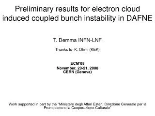
Prompt-Swept Electrons: Assumption of Proton Loss Rate Function of Beam Intensity Now, we assume proton loss rate in drift space, where ED/ES locates, is an increase function of beam intensity (reasonable from space charge). Starting from the prompt-swept values of (7uC beam, 4e-6/turn proton loss rate), we performed simultaneous fitting on both prompt swept slopes with varying a single parameter “proton loss rate” to different beam intensity, 4uC ~ 8uC beam. The searched proton loss rate to fit simultaneously experimental prompt-swept slopes becomes an almost exponential function of beam intensity. This is another possible way to estimate proton loss rate. Y. Sato ECLOUD07 8
Prompt-Swept Electrons: Profile Dependence Actual proton pulse profiles measured in PSR. Now, they seek to have square one. All my simulations for prompt-swept and recovery adopt nonotched profile except for below one. ~6uC/pulse, prompt e and swept e slopes are flipped in different pulse profiles. ORBIT suggests that a desirable proton profile depends on beam intensity. 9
Recovery of ECloud: PSR and ORBIT 7.5 uC proton pulsemeasured in PSR shows 5 turn recovery of EC peak after clearing electrons in beam gap byHV-applied electron sweeper. In ORBIT simulation, a set of parameters [SEY_max=2.0, Proton loss rate ~1E-8/turn, e- yield per lost proton=100] provides 5 turn recovery of EC to 7.5uC proton beam in field free section. Both surface current and line density of EC show the same number of recovery turns Same carry-over electrons in PB head of [2nd turn, p_loss=2E-8/turn] and [3rd turn, p_loss=1E-8]. Difference of EC peaks comes from new primary electrons (Trailing Edge Multipaction). Energy range of electrons hitting surface keeps almost same in recovery turns. The amount of carry-over electrons has little effect on the energy range. The carry over electrons before PB peak have weaker effect on EC than the new primary electrons after PB peak. 10
Inconsistency of proton loss rate between recovery estimation and prompt-swept slope fit • To perform the simultaneous fit on prompt-swept slopes, we start from the case of [SEY_max=1.7, 7uC beam, p_loss=4e-6/turn]. However, if we try to start from the case of [SEY_max=1.7, 7.5uC beam, p_loss=1e-7/turn], which matches the recovery estimation, we cannot reproduce prompt-swept slopes. • [SEY_max=2.0, 6.3uC beam] has minimum of eCloud (both prompt and swept) in lowering p_loss < 1e-8/turn. • The recovery process may be dominated by other eCloud sources. Now, in our simulation, only primary electrons from lost proton and secondary emitted electrons are considered as eCloud source. • If electrons traveled from quadrupole area to drift space are dominant, the number of recovery turns depends on the traveling time. Y. Sato ECLOUD07 11
Conclusions • Longer head beam profile is a possible way to accumulate more protons without making electron cloud larger. Proton bunch ep dynamics should be examined. • Simulated prompt-swept e of constant p_loss and SEY_max reproduces qualitative features, but not quantitative. • Introducing p_loss function to beam intensity is a possible way for quantitative discussion. A possible p_loss function that fits prompt-swept slopes simultaneously is exponential. • Comparing the number of turns of recovery process between experimental data and simulations, proton loss rate of 7.5uC beam is ~ 1E-8/turn for SEY_max=2.0 and ~1E-7/turn for SEY_max=1.7. Y. Sato ECLOUD07 12
Conclusions, cont. • Both of recovery estimation and p_loss function assumption indicates quite low proton loss rate for low beam intensity in field free straight section, and it would hard to cause ep-instability. ECloud kick on proton beam could be mostly non-straight section. • There is inconsistency between the recovery estimation of proton loss rate and the assumption of proton loss rate function of beam intensity is needed. We cannot perform the simultaneous fitting of prompt-swept electron slopes including the point of the parameters estimated by recovery process. We may need additional model of ECloud source. • The actual PSR proton bunch profiles depend on beam intensity. However, this effect does not change prompt-swept electron slopes so much. • Therefore, we need to have other model of ECloud source as shoot electrons from quadrupole area. Y. Sato ECLOUD07 13
Main Concern of ORBIT Electron Cloud Module: e-p problem Lost proton Secondary electrons e- born at wall from proton loss Captured e- before bunch released e- Proton beam bunch PSR: ~60 m in 90 m ring SNS: ~200 m in 248 m ring Tertiary electrons energy gain Secondary electrons Vacuum Chamber Wall Using Electron Cloud Module in ORBIT, we can simulate Two stream instability to captured electrons inside beam bunch (serious source of ECE) Trailing edge multipactor (big source of electrons) multipaction = increase of electrons from secondary e- emission 14