Download
1 / 27
270 likes | 397 Views
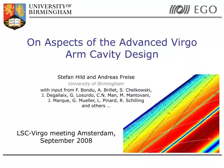
On Aspects of the Advanced Virgo Arm Cavity Design. Stefan Hild and Andreas Freise University of Birmingham

E N D
On Aspects of the Advanced VirgoArm Cavity Design Stefan Hild and Andreas Freise University of Birmingham with input from F. Bondu, A. Brillet, S. Chelkowski, J. Degallaix, G. Losurdo, C.N. Man, M. Mantovani, J. Marque, G. Mueller, L. Pinard, R. Schilling and others … LSC-Virgo meeting Amsterdam, September 2008
The Context • Advanced Virgo design is organized in several subsystems. • I work on the subsystem: “Optical simulation and Design” (OSD) subsystem-manager: A. Freise • One of the primary tasks of the OSD-subsystem is the Advanced Virgo Arm Cavity Design. LV-meeting, September 2008
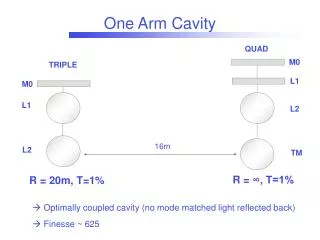
Arm Cavities: The Core of GW Detectors • In principle arm cavities are rather simple objects, consisting of just two mirrors and a space between them. • In reality one has to carefully choose the characteristics of the arm cavities: • Detector sensitivity and bandwidth. • Actual arm cavity design sets constraints for other subsystems. • Design of other subsystems sets constraints for the arm cavity design. LV-meeting, September 2008
Characteristics of the Arm Cavity to be chosen • Beam geometry (waist position) • Beam size at the test masses • Radius of curvature of the test masses • Finesse of the arm cavity • Wedges or Etalon Brief overview of the principle considerations … going a bit more into detail … (Discussion of various requirements and constraints) LV-meeting, September 2008
Beam Geometry • Where to put the waist inside the arm cavity? • Initial detectors have the waist close/at the input mirrors • Advanced detectors: Move waist towards the cavity center. • Larger beam at input mirror • Lower overall coating Brownian noise • BUT: much larger beams in the central interferometer • may need larger BS • much larger optics for input and output telescope • Non-degenerate recycling cavities might help LV-meeting, September 2008
Beam Geometry • Intuitively one would think the lowest coating noise is achieved when beam waist is at the center of the cavity (=> equal beam size at ITM and ETM), BUT: • Coating noise for ITM and ETM are different, due to their different number of coating layer: • For equal beam size ETM has higher noise. J. Agresti et al (LIGO-P060027-00-Z) LV-meeting, September 2008
Optimal Waist Position • In order to minimize the thermal noise we have to make the beam larger on ETM and smaller on ITM. • Equivalent to moving the waist closer to ITM. • Nice side effect, the beam in the central central area would be slightly smaller. Symmetric ROCs = non optimal Coating noise ITM ETM ITM ETM Asymmetric ROCs = optimal Coating noise LV-meeting, September 2008
Beam Size • Principle Rule: • The larger the beam the better the detector sensitivity • Larger beams make nearly everything else more complicated / more expensive. • Advantages of large beams: • Reduced thermal noise of test masses (especially coating Brownian) • Slightly reduced contribution from residual gas pressure • Reduced thermal lensing • Disadvantages of large beams: • Higher clipping losses • Larger test masses (especially BS, because of 45deg angle) • Larger apertures are required (vacuum system, actuators, etc) • Large telescopes (input, output, pick-off beams) • More sensitive to ROC deviations LV-meeting, September 2008
How to decide on Beam Size ? • Order of constraints: • Mirror weight (from suspension) • Aspect ratio of mirror • Coating size • Choose affordable losses • Final decision needs to trade off: • Detector sensitivity • Clipping losses inside the arm cavity (mirror/coating size) • Clipping losses inside recycling cavities (actuator geometry, BS size) • Scattered light noise contribution of the clipped light • Cavity stability (see following slides) • In the end we will probably choose a beam radius (1/e^2 in power) of about 5.5 to 6.5cm. More detail in Hild et al: VIR-038B-08 LV-meeting, September 2008
Cavity Stability and Choice of ROCs • ROCs and beam size are connected. • We want ROCs that give stable cavity: • Account for potential manufacturing accuracy • AdVirgo example: L = 3000m, beam radius at ITM and ETM = 6cm => ROCs of 1531m are required. • Deviation of only a few ten meters can make cavity instable. • Additional problem: polished spheres are not spherical. • Avoid resonance of higher order optical modes • Use mode-non-degeneracy as figure of merit Example of non-spherical mirror from initial Virgo Average ROC depends on beam size used for fitting LV-meeting, September 2008
Cavity Stability and Choice of ROCs • Definition of mode-non-degeneracy: • Gouy-phase shift of mode of order l+m: • Mode-non-degeneracy for a single mode is: • Figure of merit for combining all modes up to the order N: Instablity LV-meeting, September 2008
Choice of ROCs/beam size:Sensitivity vs Mode-non-degeneracy • In general mode-non-degeneracy and sensitivity go opposite. • Asymmetric ROCs are beneficial: • For identical mode-non-degeneracy (parallel to arrows in lower plot) we can increase sensitivity (parallel to arrow in upper plot) by going towards the upper left corner. • This means making beam larger on ETM and smaller on ITM. LV-meeting, September 2008
Arm Cavity Finesse • Advantages of higher finesse: • Reduced noise coupling from MICH to DARM • Less thermal load in central interferometer • Disadvantages of higher finesse: • More sensitive to losses inside the arm cavities • Increased coating Brownian noise of the ITM (due to more required coating layers • Power problems (parametric instabilities)? • In the end we will probably go for a finesse between 400 and 700. LV-meeting, September 2008
Characteristics of the Arm Cavity to be chosen • Beam geometry (waist position) • Beam size at the test masses • Radius of curvature of the test masses • Finesse of the arm cavity • Wedges or Etalon Brief overview of the principle considerations … going a bit more into detail … (Discussion of various requirements and constraints) LV-meeting, September 2008
Wedges vs Etalon Input mirror with wedge: • Used by initial LIGO • Reflected beams from AR coating can be separated from main beam => pick-off beams provide additional ports for generation of control signals. • No etalon effect available. Input mirror etalon: • Initial Virgo has no wedges in the input mirrors • The etalon effect could be used for adjusting the cavity finesse (compensating for differential losses) • If etalon effect is not controlled it might cause problems LV-meeting, September 2008
Possible design option: Wedges at input mirrors and etalon effect at end mirrors • Wedge at input mirrors: • Allows for additional pick-off beams • Use etalon effect at end test mass • Tune etalon to balance arms => reduce noise couplings => might speed up commissioning • Tune etalon to change readout quadrature in DC-readout. • Replace AR-coating by a coating of about 10% reflectivity. • Ideally use a curved back surface (same curvature as front). LV-meeting, September 2008
Wegdes at Input Mirrors • Need a wedge large enough to separate beams within about 5 meter (distance ITM to BS). • For 6cm beam radius a wedge of about 1.5 deg is required. • High hardware impact (larger vacuum tube in centeral IFO, more optical elements) More detail in J. Marque talk LV-meeting, September 2008
Differential Arm Length Noise from vertical Movement of wedged Input Mirrors • Lateral movement of a wedged mirror cause length sensing noise. • Need to do a projection of seismic noise to DARM: • Not limiting within the detection band. • Please note: No actuation noise considered. More detail in Hild et al: VIR-037A-08 LV-meeting, September 2008
Balancing Range due to Etalon Effekt • Examples of figures of merit: • Transmittance of end mirror (etalon) • Finesse of arm cavity LV-meeting, September 2008
Etalon changes Optical Phase • When changing the etalon tuning the optical-phase changes as well. (noise!) • The two etalon surfaces build a compound mirror, whose apparent position depends on the etalon tuning. LV-meeting, September 2008
Requirement for Temperature Stability of Etalon Substrate • Certain temperature stability of Etalon substrate required to not spoil AdV sensitivity • Can compare this requirement to substrate thermal noise • Not limiting. • Please note: Did not consider technically driven temperature fluctuations. More detail in Hild et al: VIR-058A-08 LV-meeting, September 2008
Optical Design: Check System Integrity for Deviations from Specs • A deviation in the relative misalignment (parallelism) and relative curvature of the two etalon surfaces: • Imperfect wave front overlap… • Reduces tuning range … • Beam shape distortions … • Two methods for analysis: • FFT based code (Waveprop) • Coupling coefficients LV-meeting, September 2008
FFT-simulation of a Non-Perfect Etalon • Using R. Schilling’s WaveProp, http://www.rzg.mpg.de/~ros/WaveProp/ • Cross checking with DarkF. DarkFstatus_08_03_2006.ppt • Parameters: • Field: 256x256 • Computing 3000 roundtrips • End mirror front: • 50ppm transmission • End mirror back: • Varying three parameters • Reflectance • Misalignment (parallelism) • Curvature mismatch LV-meeting, September 2008
Analytic Approximations using Higher-Order Modes • Reflection at a (slightly) misaligned component can be characterised by scattering into higher order TEM modes • This model is valid for misalignments below half the diffraction angle (paraxial approximation) • The amplitude in the outgoing fields is given by coupling coefficients knmnm • For small misalignments the coupling coefficients knmnm can be approximated. The amount of light which remains in a TEM00 mode is given by: (q is the Gaussian beam parameter of the light at the mirror) LV-meeting, September 2008
Tuning Range of imperfect Etalon • Requirements for Etalon manufacturing accuracy: • Parallelism better than a few urad. • ROC deviation: uncritical LV-meeting, September 2008
Influence of Etalon Tuning to other Subsystems: Example Alignment • Evaluation of global alignment sensing and control. • Simulated Ward-technique and Anderson-technique. • For perfect etalon: No surprises. • For non perfect etalon: • Coupling of etalon rear surface misalignment is 4 to 5 orders below etalon front surface misalignment. • Amount of first order optical modes inside the arm cavity origination from etalon imperfections is found to be negligible. More detail in Mantovani et al: VIR-027A-08 LV-meeting, September 2008
Summary • Presented overview of how to choose the main characteristics of the Advanced Virgo arm cavity. • More detailed analysis for wedges vs etalon: • Presented potential design (wedged ITM, etalon at ETM) • Presented requirements for: • Seismic isolation (wedge) • Temperature stability of etalan (optical phase noise) • Manufacturing accuracy of the etalon • Checked for negative implications of other subsystems: • Alignment sensing and control • Publication on the arxiv: Hild et al: “Using the etalon effect for in-situ balancing of the Advanced Virgo arm cavities” arXiv:0807.2045 Thanks for the helpful input from the LSC review ! LV-meeting, September 2008