Download
1 / 22
220 likes | 322 Views
Automation of the Lock Acquisition of the 3 km Arm Virgo Interferometer. F. Carbognani for The Virgo Collaboration ICALEPCS - Geneva 14 October, 2005. Outline. Virgo Experiment Control and Monitoring Automation Layer Real-Time and Fast Automation Layer Lock Acquisition Procedure

E N D
Automation of the Lock Acquisition of the 3 km Arm Virgo Interferometer F. Carbognani for The Virgo Collaboration ICALEPCS - Geneva 14 October, 2005
Outline • Virgo Experiment • Control and Monitoring Automation Layer • Real-Time and Fast Automation Layer • Lock Acquisition Procedure • Automation Performances • Conclusions
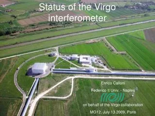
Virgo Experiment • Aim: Detection of the gravitational waves emitted by astrophysical sources • Consists of a power recycled Michelson interferometer with 3 km long Fabry-Perot cavities in its arms
Working Point • The mirrors must be aligned with a precision of a fraction of a micro-radian • The relative distance of the suspended optics must be controlled within a pico-meter • Working point maintained by using several digital feedback loops working at 10 kHz.
Automation • Two automation layers: • A control and monitoring automation layer that uses a script-like language to monitor the needed DAQ channels and to control the first automation layer. • A real-time and fast automation layer implemented into the sub-system servers involved in the different loops.
Automation Layers Control and monitoring automation layer Automation sequence Data Data Acquisition (DAQ) Commands Real-time and fast automation layer Global and Local Control Loops Data
Automation of Locking Procedure (ALP) • Use the data acquired by the DAQ to compute the state of any subsystem by processing the collected channels related to it. • According to the subsystem state, actions can be performed using the system calls or directly with messages in Cm format. DAQ AlpRecycled (master) DAQ Data Display Action Action Sub-systems servers AlpDet AlpAli AlpSa Action
ALP Macros • Set of code related to the same automation phase and a script language to define the macro’s content. • Macro functionalities: • ALP variables declaration, • new DAQ channels can be created by performing arithmetic operation (+,-,*,/) between input channels, • DAQ channel’s properties can be computed in the time domain (mean,min,max,rms,range) or in frequency domain (FFT, bandRMS …) and stored into ALP variables, • Arithmetic operations (+,-,*,/) between ALP variables, • test and loop conditions on ALP variables, • commands can be sent to act on given sub-system servers, • direct call of a macro
Alignment and Longitudinal Controls • Global Control • Processes signals coming from the photodiodes and sends control signals to suspensions DSP. • ALP drives: • switch between algorithms (Sensing, Filtering or Driving) • “on-the-fly” parameters changes • Gc state transitions Photodiode Signals Mirror Corrections Locking Frequency: 10 kHz Alignment Frequency: 500 Hz ITF Control
Local Controls Mirror Local Control Longitudinal swing reduced to tenths of mm/s by Inertial Damping. Tidal effects compensated by acting to the top stage, Tidal control. Angular mirror displacements reduced to fraction of mrad by Local Controls Alp drives: switching off the inertial damping loops swapping from local controls to angular drift controls switching the coil drivers to low noise mode
The Injection System • First Stage of Frequency Stabilization and Automatic Beam Positioner (ABP) control loop started by ALP at init time • Second Stage (SSFS): one ITF error signal as frequency reference engaged (and disengaged when needed) by the Global Control. In case of problems ALP can disengage the loop within few seconds delay
Automation Layers (Detailed) Locking and Alignment Servo-Loops TimingSystem Mirror controls and Injection Photodiodes Readout Global Control Calibration LocalServo-loops DAQ Frame Building Low latency Alp Automation Frame Buiding Last stage Data Archiving Data Processing
LW lw lrec lN LN Locking Procedure The goal of a lock acquisition procedure is to bring the ITF on its working point, by controlling its independent longitudinal lengths 4 lengths to be controlled: • MICH = ln-lw • PRCL= lrec+(lN+ lw)/2 • CARM= LN+LW • DARM= LN-LW By using a carrier beam phase modulated at 6 MHz and the Pound-Drever-Hall technique all the four lengths can be reconstructed by mixing the signals coming from photodiodes placed at different output ports of the interferometer.
Locking Procedure • For the ITF locking a novel strategy, called Variable Finesse Locking has been adopted • Basic Idea: the ITF is locked on the half (gray) fringe, then brought sequentially to the dark fringe through several steps. During those steps the control scheme is changed. • The lock acquisition procedure embeds this strategy and consists in two main sequences: • Pre-alignment Sequence • Locking Sequence
Pre-alignment sequence • This sequence, not always executed at each lock acquisition attempt, is implemented by the following three macros: • “Direct_Beam_Alignment”: Alignment of the direct beam into the North and the West arms. • “Cavities_Alignment”: North and West arm cavities independent locking, their non-linear alignment (when really needed) and their linear alignment. • “PR_Coarse_Alignment”: Non-linear alignment of the PR mirror, with respect to the arm cavities mirror alignment performed in the previous macro.
Locking sequence Implemented by a single macro, called “Lock_Step_request”. • STEP 1 : Lock acquired with the PR mirror misaligned by 10 mrads and the ITF on the grey fringe (i.e. Dark Fringe at 50%) • STEP 2 : A boost filter added to the PRCL and MICH loops. Dark Fringe from 50 to 40%. • STEP 3 : CARM loop controlled by the SSFS. • STEP 4 : PR mirror aligned and consequently the power stored in the ITF increases • STEP 5 : Dark Fringe from 40 to 20%. A boost filter added to DARM loop. • STEP 6 : Dark Fringe from 20 to 8%. • STEP 7 : Dark Fringe from 8 to 5%. • STEP 8 : Final step to Dark Fringe. Transition of the MICH loop error signal from the B1p DC signal to the B5 demodulated. Angular drift control switched on.
Locking sequence • STEP 9 : Transition of DARM loop error signal from the noisy B8 to the less noisy B1p demodulated. • STEP 10 : Output Mode Cleaner (OMC) put on resonance, transition of DARM loop error signal from B1p to B1. After the transition all the noisy mirror motion dampers are switched off. • STEP 11 : A filter having a reduced band and a high roll-off is added the MICH loop. • STEP 12 : Activation of the tidal control, swapping to low-noise coil drivers. • STEP 13 : Re-adjustment of demodulation phase and gain of PRCL loop. • STEP 14 : A fraction of the MICH correction signal is sent in counter-phase to the end mirrors. • STEP 15 : Permanent lines are added to the different mirror corrections for ITF calibration.
Performances • Lock Acq procedure fully automated Low noise OMC lock Lock to DF variable finesse SSFS 5 mins
Step1 to Step15 duration distribution Performances • Duty cycles:Locking: 89% • Science mode (locked and stable ITF) : 86% Commissioning run C6:Jul 29 – Aug 13, 2005 Percentage of time spent on the Step1 – Step 15 sequence: 5.29%
Conclusions • The automation has allowed to define a reproducible lock acquisition sequence, thus to stabilize the commissioning environment • Automation has showed all his effectiveness in supporting the ITF operations during commissioning and run periods • The Virgo machine is being provided with a tool allowing the operator to easily, reliably and quickly drive the machine into the working state. • The planned future improvements are: • Adding more controls and checks inside macros • Monitoring of all Servers status and check of correct handling of the requested commands. • Automated subsystem failure recovering plus automated re-locking. • Performance optimisation on critical servers currently generating latency peaks.