Download
1 / 8
80 likes | 182 Views
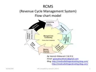
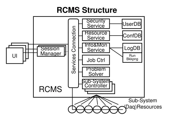
RCMS Structure. Security Service. UserDB. ConfDB. Resource Service. UI. Info&Mon Service. LogDB. UI. Services Connection. Session Manager. UI. Run Bkkpng. Job Ctrl. Problem Solver. Sub-System Controller. RCMS. Sub-System (Daq)Resources. RCMS Layout. UI. UI. UI. RCMS.

E N D
RCMS Structure Security Service UserDB ConfDB Resource Service UI Info&Mon Service LogDB UI Services Connection Session Manager UI Run Bkkpng Job Ctrl Problem Solver Sub-System Controller RCMS Sub-System (Daq)Resources
RCMS Layout UI UI UI RCMS Session Manager Services Services Services Connection EVB Ctrl TRG Ctrl CS Ctrl DCS Ctrl EVF Ctrl EVM BUs RUs Mu Cal Glbl EVF Sub-System TRG Sub-System EVB Sub-System DCS Sub- System CS Sub- System
Interaction with the sub-systems EVB BU RU • The Control Network topology of the sub-systems. Possible hierarchies introduced by the DAQ slicing • Commands submission and information (errors, monitor, etc.) collection performances inside a given sub-system. • Where all this is reported? Do we need it? • Interaction with DCS and CS. (?) BU Slice X sub-system EVM Sub-System Controller DAQ resource
Run Sessions and Partitions (i) UI UI UI UI run session A run session B UI UI RCMS Session Manager Session Manager Services Services Services Connection EVB Ctrl TRG Ctrl CS Ctrl DCS Ctrl EVF Ctrl EVM BUs RUs Mu Cal Glbl EVF Sub-System TRG Sub-System EVB Sub-System DCS Sub- System CS Sub- System
Run Session and Partitions (ii) • RCMS should interact with the Trigger sub-system to get/set the available partitions. • Are they defined and stored in the Resource Service? • Who set the trigger partitions? • The same for DCS.
Run Definition homogeneous conditions homogeneous conditions Start Stop Start Stop CLASSIC Run # X+1 Run # X Change Conditions Store new conditions Change data file LHC “spill” LHC Start Stop condition Y changed condition Z changed Condition DB dump conditions Fast Reset mini Run A B C D E
IMS & Run Conditions • We assume the run conditions coming from all the sub-systems (including trigger and DCS) are managed by the Information and Monitor System. Is this true? • Is the message definition adequate for handling this type of information? • DB performances requirements must be defined much better. If any “natural” hierarchy is defined (e.g. the one introduced by the daq slicing), it can be reflected in the DB design helping in this way the scalability of the system. • The system has O (10000) (?) objects with related status to save every time a dump condition is required. • we could have an incremental dump: we save all the conditions at start time and then after that only the ones have been changed. • we need to know size, types, etc. of the parameters characterizing the detectors setup (HV, LV, P, T, etc.). How we can get them? How fast we can read them? any defined hierarchy? • Same for the trigger system.
IMS message definition T, Type, Id, Specific Fields, Source_Id Time Stamp Message Source Id • Message Type: • Errors • Generic • Status Change • Monitor Message Id According to Type e.g. for Errors: - Severity Level (0=warning) - Description