Download
1 / 21
210 likes | 328 Views
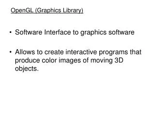
Graphics Systems and OpenGL. Business of Generating Images. Images are made up of pixels. RGB. RGB Color cube (what we use in computer graphics). Other color spaces include HSV, YUV, YCrCb, and YIQ. The “goal” of computer graphics. Solve the function Red @ a pixel is f(i,j)=…

E N D
Business of Generating Images • Images are made up of pixels
RGB RGB Color cube (what we use in computer graphics) Other color spaces include HSV, YUV, YCrCb, and YIQ
The “goal” of computer graphics • Solve the function • Red @ a pixel is f(i,j)=… • Green @ a pixel is f(i,j)=… • Blue @ a pixel is f(i,j)=…
Two Dimensional Images +Y • Images (at least the ones in this class) are two dimensional shapes. • The two axes we will label as X (horizontal), and Y (vertical). Y Axis (0,0) X Axis +X
Hardware Pipeline Input Computation Output We want to draw a rectangle, how do we describe it to a computer? Model (n) - object description that a computer understands.
Partition the space 1. Define a set of points (vertices) in 2D space. 2. Given a set of vertices, draw lines between consecutive vertices. (7,9) (14,9) (7,3) (14,3) Vertex (pl. Vertices) - a point in 2 or 3 dimensional space.
Record every position Bitmap - a rectangular array of bits mapped one-to-one with pixels.
Representing Objects • Most common method is the VERTEX method. Define the object as a set of points with connectivity information. • Why is connectivity important? Connectivity - information that defines which vertices are connected to which other vertices via edges. Edge - connects two vertices
A Simple Program Generate a square on a solid background
simple.c #include <GL/glut.h> void mydisplay(){ glClear(GL_COLOR_BUFFER_BIT); glBegin(GL_QUADS); glVertex2f(-0.5, -0.5); glVertex2f(-0.5, 0.5); glVertex2f(0.5, 0.5); glVertex2f(0.5, -0.5); glEnd(); glFlush(); } int main(int argc, char** argv){ glutCreateWindow("simple"); glutDisplayFunc(mydisplay); glutMainLoop(); }
Practical Approach • Process objects one at a time in the order they are generated by the application • Pipeline architecture: • All steps can be implemented in hardware on the graphics card Input Computation Output application program display
simple.c #include <GL/glut.h> void mydisplay(){ glClear(GL_COLOR_BUFFER_BIT); glBegin(GL_QUADS); glVertex2f(-0.5, -0.5); glVertex2f(-0.5, 0.5); glVertex2f(0.5, 0.5); glVertex2f(0.5, -0.5); glEnd(); glFlush(); } int main(int argc, char** argv){ glutCreateWindow("simple"); glutDisplayFunc(mydisplay); glutMainLoop(); }
Synthetic Camera Model projector p image plane projection of p center of projection
Vertex Processing • Much of the work in the pipeline is in converting object representations from one coordinate system to another • Object coordinates • Camera (eye) coordinates • Screen coordinates • Every change of coordinates is equivalent to a matrix transformation • Vertex processor also computes vertex colors
Projection • Projection is the process that combines the 3D viewer with the 3D objects to produce the 2D image • Perspective projections: all projectors meet at the center of projection • Parallel projection: projectors are parallel, center of projection is replaced by a direction of projection
Primitive Assembly Vertices must be collected into geometric objects before clipping and rasterization can take place • Line segments • Polygons • Curves and surfaces
Clipping Just as a real camera cannot “see” the whole world, the virtual camera can only see part of the world or object space • Objects that are not within this volume are said to be clipped out of the scene
Rasterization • If an object is not clipped out, the appropriate pixels in the frame buffer must be assigned colors • Rasterizer produces a set of fragments for each object • Fragments are “potential pixels” • Have a location in frame bufffer • Color and depth attributes • Vertex attributes are interpolated over objects by the rasterizer
Fragment Processing • Fragments are processed to determine the color of the corresponding pixel in the frame buffer • Colors can be determined by texture mapping or interpolation of vertex colors • Fragments may be blocked by other fragments closer to the camera • Hidden-surface removal