Download
1 / 38
390 likes | 516 Views
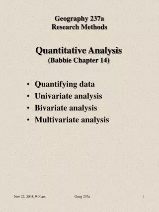
Performing Quantitative Analysis with Remotely Sensed Imagery in ENVI …we will begin shortly. Performing Quantitative Analysis with Remotely Sensed Imagery in ENVI. The phone lines will be muted for sound quality.

E N D
Performing Quantitative Analysis with Remotely Sensed Imagery in ENVI…we will begin shortly
Performing Quantitative Analysis with Remotely Sensed Imagery in ENVI • The phone lines will be muted for sound quality. • Please direct questions to the Chat window. My colleague will be available to answer any questions. • The presentation will be recorded and posted to the ITTVIS website
Survey! • Do you work on a Windows, Mac, or Unix machine?
Topics to Cover • Concepts in Remote Sensing • Why calibration and atmospheric correction are important data pre-processing tasks • Basic tools in ENVI to account for general atmospheric effects • Advanced tools in ENVI for robust atmospheric correction • The difference between raw data, radiance, and reflectance data • Applications that rely on atmospherically corrected and calibrated data
Sun - Sensor Pathway Sensor Path Radiance (scattered light) Solar Irradiance Absorbed by atmospheric gases Radiance (reflected and emitted energy) absorbed
(From Valley, 1965) 0.25 Solar Spectrum 0.20 Blackbody at 5900K Solar irradiance outside atmosphere Solar irradiance at sea level 0.15 O3 Spectral Irradiance (W/m2mm) H2O 02, H2O H2O 0.10 H2O H2O H2O 0.05 H2O, CO2 H2O, CO2 H2O, CO2 0.0 0.2 0.4 0.6 0.8 1.0 1.2 1.4 1.6 1.8 2.0 2.2 2.4 2.6 2.8 3.0 3.2 Wavelength (mm)
The Electromagnetic Spectrum NEAR- INFRARED (NIR) SHORT WAVE INFRARED (SWIR) VISIBLE (VIS) 1.0 0.9 O2 CO2 H2O O2 O3 0.8 H2O CH4 0.7 O2 0.6 H2O Atmospheric Transmittance H2O 0.5 0.4 H2O H2O CO2 0.3 H2O 0.2 0.1 0.0 400.0 700.0 1000.0 1300.0 1600.0 1900.0 2200.0 2500.0 Wavelength (nm) VISIBLE MICRO- WAVE GAMMA UV INFRARED RADIO 1 m 10 m 1 nm 10 cm 1 mm 1 mm 1 km 10 mm 10 nm 1 cm 10 km 100 m 100 mm 100 nm 10-6 nm 10-4 nm 10-5 nm 10-3 nm 10-2 nm 10-1 nm 100 km
Raw to Radiance (Data Calibration) Raw DN includes: Surface Reflectance, Solar irradiance curve, Atmospheric effects (scattering, absorption), Variation in illumination due to topography, Instrument response Raw to Radiance – remove instrument effects Instrument calibration required to derive radiance coefficients Raw DN * coefficients = Radiance
Atmospheric Effects and Surface Reflectance on Radiance irradiance wavelength Radiance irradiance wavelength Atmosphere Radiance with atmospheric effects irradiance wavelength Atmosphere with atmospheric effects and ground reflectance
Radiance to Reflectance L0(l)=Lsun(l) T(l) R(l) cos(q) + Lpath(l) L0(l) = observed radiance at sensor Lsun(l) = Solar irradiance above atmosphere T(l) = total atmospheric transmittance R(l) = surface reflectance q = incidence angle Lpath(l) = path scattered radiance Conversion methods generally result in “apparent reflectance” because of topographic slope and aspect effects – variations in illumination are not corrected Reflectance data scaled to get to integer data (typically x 10,000)
The Importance of Calibration and Atmospheric Correction • To compare multi-date images – some data sets even have different atmospheric properties across a scene • To compare data sets from different sensors • Needed for quantitative analysis, e.g., working with field data • convert to physical units – Radiance units: watts/sr*cm2*nm • When using band ratios such as vegetation indices • Reflectance data needed to compare data spectra with library reflectance spectra – helps in identifying materials based on their absorption features • Or to use spectral library to map materials, image must be in reflectance.
Advantages of Reflectance Data • Spectral features much more apparent in reflectance data than radiance • The shapes of spectra are principally influenced by the chemical and physical properties of surface materials • Reflectance data may be analyzed using spectroscopic methods that isolate absorption features and relate them to chemical bonds and physical properties of materials.
Survey! • Do you work with raw, radiance, or reflectance data? • HSI or MSI data?
Multispectral Data Preprocessing raw radiance
Multispectral Data Preprocessing reflectance (with scattered light) reflectance
Hyperspectral Data Preprocessing • Data from Santa Barbara, CA • With radiance data, the overall shape of this spectrum is strongly a function of the solar irradiance spectrum and absorption by atmospheric gases, especially water vapor water vapor
Conversion to Reflectance Methods • Scene-derived corrections – in-scene statistics are used • Internal Average Relative Reflectance (IAR) • Flat Field • Log Residuals • Quick Atmospheric Correction (QuAC) • Ground-calibration methods • Empirical Line • Radiative transfer models • FLAASH
Internal Average Relative Reflectance (IAR) • The Internal Average Reflectance (IAR) approach uses the mean radiance of all the pixels in the image as a correction factor. • The individual radiance values in each pixel are divided by this mean radiance to estimate reflectance. • Removes common things • However, introduces artifacts
Flat Field • Flat field - large, bright, homogenous target • The individual radiance values in each pixel are divided by the mean radiance of the flat field • Removes things in common
Log Residuals Designed to remove solar irradiance curve, atmospheric transmittance, instrument gain, topographic effects, and albedo effects from radiance data Defined as the input spectrum divided by the spectral geometric mean, then divided by the spatial geometric mean, creating a pseudo reflectance image First calculate the spectral and spatial geometric means. Geometric means are calculated using logarithms of the data values and are used because the transmittance and other effects are multiplicative. The spectral mean is the mean of all bands for each pixel and removes topographic effects The spatial mean is the mean of all pixels for each band and accounts for the solar irradiance, atmospheric transmittance and instrument gain Each image data value is then divided first by the spectral and then by the spatial mean
QuAC QUick Atmospheric Correction is fast The approach is based on the finding that the spectral standard deviation (or endmember mean spectrum) of a collection of endmember spectra in a scene, is essentially spectrally flat Works even when the sensor was not properly calibrated, or when the solar illumination intensity is unknown Multi- or hyperspectral data can be raw, radiance, or apparent reflectance
QUAC continued Does not work well in a scene that is not spectrally diverse. The scene should have several different materials. The scene should have dark materials or shadows QuAC is Batchable
Empirical Line Channel x bright target Slope=gain dark target Intercept=offset Ground reflectance dark target Image radiance bright, homogenous target Reflectance=gain x radiance + offset If only one spectrum is used, then the regression line will pass through the origin
Advanced Tools in ENVI for Conversion to Reflectance • Radiative Transfer – based • Models are developed that describe the radiative transfer of sunlight in its physical interaction with the gases and particles in the atmosphere, its interaction with the surface, and its transmission along a different path upward through the atmosphere to the sensor. • These models describe the solar irradiance curve, the absorption and scattering by atmospheric gases, and the reflectance from surface materials, all as a function of wavelength of electromagnetic radiation and the directional angles of the sun and sensor. • Errors arise from inadequate definition of the solar irradiance function, variations in the illumination, imperfect models that describe absorption by atmospheric gases, and any mis-calibration of the sensor.
FLAASH FLAASH 4.1 – Fast Line of Site Atmospheric Analysis of Spectral Hypercubes Supports many hyperspectral and multispectral Instruments: AVIRIS, HYDICE, HyMap, Probe-1, CASI, AISA, and HYPERION, Landsat, SPOT, IRS, IKONOS, QuickBird, ASTER, WorldView 2, etc. Incorporates MODTRAN4 radiative transfer code First, the optical characteristics of the atmosphere are estimated by using theoretical models. Then, various quantities related to the atmospheric correction are computed by the radiative transfer algorithms given the atmospheric optical properties. Then, the data can be corrected by inversion procedures that derive the surface reflectance. Handles clouds, cirrus and opaque. Gases corrected for: water vapor, ozone, oxygen, carbon monoxide, carbon dioxide, methane, and nitrous oxide Water vapor the most variable and most important Water modeled using three-band ratios around either the1135, 940 or 820 nm absorptions. Correction only possible where band positioning is appropriate. Assumes that the surface is horizontal and has a Lambertian (diffuse) reflectance
FLAASH Parameters Sensor Type Band passes and pixel size Atmospheric Model - select appropriate model Water Retrieval – to solve radiative transfer equations, water column needed 1135 nm is default – use unless there are materials in scene with absorptions at that wavelength then use 940 nm or 820 nm absorption Aerosol Model – not critical if visibility over 40 km Initial visibility – Clear: 40 to 100 km, Moderate Haze: 20—30 km, Thick Haze: 15 km or less Spectral Polishing – well-behaved spectra used for calculation of gain factor. Used to remove artifacts due to: Errors in radiative transfer models/calculations Low signal in certain portions of the spectrum Mis-calibration of sensor Wavelength Recalibration – actual band positions determined from atmospheric features. Data sets can be re-run with new wavelength file.
EFFORT Polishing – stand alone routine Empirical Flat Field Optimal Reflectance Transformation Bootstrapped solution – “well behaved” flat reflectance sample spectra selected with replacement from all spectra bootstrapping – sampling with replacement such that selected set can be treated as the entire population Statistically mild gain (close to 1) and offset (close to 0) are calculated for each band – similar to empirical line correction End result – artifacts removed and spectra more of a true indication of sensor SNR. Spectra can be more accurately compared to spectral library spectra
Raw Data versus Calibrated/Corrected Results raw data Maximum likelihood classification radiance data Maximum likelihood classification input data color infrared
Raw Data versus Calibrated/Corrected Results raw data Maximum likelihood classification radiance data Maximum likelihood classification input data color infrared
Raw Data versus Calibrated/Corrected Results reflectance data NDVI Dark-corrected reflectance data NDVI input data color infrared
Hyperspectral Radiance versus Reflectance Data reflectance radiance input data
Hyperspectral SAM Results Comparison reflectance data SAM result radiance data SAM result input data color infrared false positives false positives
Some Applications that Rely on Atmospherically Corrected and Calibrated Data • Vegetation studies • NDVI, pigments, lignin and cellulose, species and community mapping, • Geological studies • Mineralogy, soils, rock types • Coastal and inland waters • Chlorophyll, suspended sediments, bottom composition • Snow and ice • Snow cover fraction, grain size • Environmental • Oil spills, other contaminants • Man-made infrastructure
For more information about ENVI’s capabilities or to request an evaluation: www.ittvis.com sales@ittvis.com 303.786.9900 For upcoming seminars and training, please visit: www.ittvis.com/EventsTraining