Download

1 / 38
380 likes | 504 Views
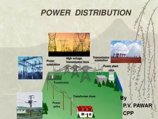
Industrial Design Application for Power Distribution over Extra-Long Distances. Or Lots of Wire Little Vd. Robert A Durham, PE New Dominion, LLC Tulsa, OK. Marcus O Durham, PhD, PE THEWAY Corp Tulsa, OK. Introduction. Typical petrochemical installations: Geographically confined

E N D
Industrial Design Application for Power Distribution over Extra-Long Distances Or Lots of Wire Little Vd Robert A Durham, PE New Dominion, LLC Tulsa, OK Marcus O Durham, PhD, PE THEWAY Corp Tulsa, OK
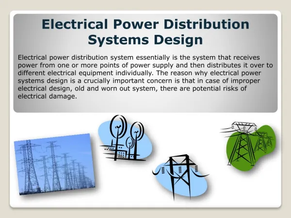
Introduction • Typical petrochemical installations: Geographically confined Large loads • Utility installations: Geographically dispersed Distributed loads • Large loads over large distance cause unique problems
IntroductionGoals • Downtime eliminated • Protection system isolates faults • Total system voltage > 95% • Contingency is bi-directional feed • Adequate Ampacity to prevent sags
Loads • Primary loads • 150 – 400 Hp, 2400 VAC • 2 pole, low inertia • Steep speed-torque curve • Centrifugal pumps • Eff 80%, pf 78%
Loads Secondary Loads • 1000 Hp, 2400VAC • 4 pole, induction machines • Reciprocating compressors
LoadsStarting • Primary Loads (150 – 400 Hp) • Generally started across the line • Some use VFD • Inherent robustness of system adequate
LoadsStarting • Secondary Loads (1000 hp) • Vd caused by starting trips primary load • Need soft start – 60% FLA
Geography • System spread: over 900 square miles • Main trunk line: 25 miles in length • Radial lines: 1 – 12 miles long • Each radial: 1 – 5 MW
Design Philosophy • Difference between utility & industrial - purely a matter of economics • Utility: Downtime = loss of electric sales • Industrial: Downtime = loss of production sales • Damage to production may be unrecoverable • Industrial has much larger risk
Construction Management • Emphasis on elimination of maintenance • Contractors used on day work basis
Environmental Controls • ROW clearing • 60’ - 100’ wide • leave root balls for erosion control • treat with herbicide • 95% of recovered product is waste • Extensive load shedding and motor control used to ensure responsible disposal
Meteorological Considerations • Temperature range: –23C to 47C • Thunderstorms: 55 isoceraunic days • Ice: “Heavy” ice loading area • Wind: Basic winds 80 MPH • Severe: Heart of Tornado Alley • Seismic: Occasional earthquake • No applicable industry standards • Build above utility standards
Table 1 Line Construction Practices Conductor Industrial Utility Size (ACSR) Span Span 477 kcmil 64 m (210 ft) 76 m (250 ft) #4/0 69 m (225 ft) 76 m (250 ft) #1/0 69 m (225 ft) 90 m (295 ft) #2 76 m (250 ft) 90 m (295 ft) Add 4 poles / mile (1.63 km)
Results of Philosophy • Recent winter storm • Severe icing in region • Some areas w/o utility for 30 days • The system discussed here • single incidence of blown fuses • no line on ground
Supply • Most loads this size served from transmission • Limited number of 69 /138 kV lines in area • Supply taken at distribution levels
Supply • Supply taken at distribution levels • Many areas served from REC lines • Some dedicated 138/25kV subs • At dedicated subs, voltage as high as 120% assists with voltage conditions
Electrical Constraints Wire size based on ampacity- Sag Here, voltage drop is main concern Low power factor contributes Main trunk line : 477 ACSR Main branch feeders: 4/0 ACSR Individual load service: #2 ACSR
Capacitors • With no correction – system at 80% pf • Standard – place caps on lines
Capacitors • Extensive load shedding system can trip large quantities of load • Resulting excessively leading pf can damage equipment, cause trips • Must switch caps with load shed • Place oil reclosers or sectionalizers at each 25kV cap bank
Capacitors - Options • Place medium voltage caps at motors • Automatically switch w/ load • Nearest to load • Can downsize transformers and fuses • Cost less than oil switches
Overcurrent Protection • Two unique systems • Protect motor & transformer (load point) • Protect system from cascading faults
Overcurrent Protection • Load points protected with fused cutouts • Fuse links sized tightly to avoid extra trips • Use high speed (X speed) fuse links
Overcurrent ProtectionMain Line Cutouts • High risk of single phasing motors • High rating of fuses makes coordination with utility difficult • Electric storms cause unacceptable # of outages due to arrestor operation • Outages require electrician to restore power = excessive downtime
Overcurrent ProtectionMain Line Reclosers • Oil reclosers placed at utility supply point and each main branch feeder (2MW or greater load) • Oil reclosers placed along trunk every 10 MW
Overcurrent ProtectionMain Line Reclosers • Main line reclosers use processor relays • Branch reclosers can use • plug-setting type relays • processor when available
Lightning • Lightning is a major concern in this area • 55 isoceraunic days per year • odds of induced or direct strike high • Lightning arrestors • placed every 1500 – 1700 feet • Excellent ground system is imperative
Effective Grounding Multi-point ground required Personnel safety Equipment protection Length of system #1 factor L of ground wire length Long distance = high Z • Single point ground Does Not Exist
Computer Modeling Selection • Cost - $10,000 • Cost - Approximately two weeks engineering time • Numerous products on the market • Two are usable for this type design • One was selected based on overhead line modeling capabilities
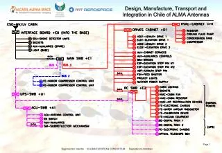
Computer ModelingProcedures • Build single motor model for each service point • Create motor subsystem consisting of motor, transformer, switches, etc • Combine several subsystems on a sub-trunk feeder
Computer ModelingProcedures • Tie sub-trunk feeders to main trunk line • Add detail for protection devices, fuses, switches, capacitor, microprocessor relays, motor protection devices
MOTOR1 184 HP FUSE101 CONT5 FUSE12 CAP27 120 kvar T6 225 kVA SCHEMATICMOTOR MODEL FUSE13
Computer ModelingUses • Original model created as design tool before any construction • Allowed alternatives for conductor size, lengths, protection • Used model during construction for communication with crews
Computer ModelingUses • Refined model for operations – voltage drop, current, power factor • Updated model for system upgrades • Recent upgrade netted 8% reduction in electric bill – 6 month payout
Review Goals • Downtime eliminated • Protection system isolates faults • Total system voltage > 95% • Contingency is bi-directional feed • Adequate Ampacity to prevent sags
Computer modelingSystem Results • Under normal conditions voltage drop is 8% • Supply voltages at 115% allow for continuous operation under contingency • Advanced coordination of protection allowed advanced devices with little on-site prep • Properly coordinated protection shields equipment w/o unnecessary downtime
Conclusions • Uncommon: spread out industrial system • Semi-utility design + uniquely industrial ops • Enhanced specs, > cost, more reliable • w/o computer, complex system impossible • Design, construction, operations, mgt. • One engineer
Conclusion • ConclusivelyWith the aid of modern tools, a system can be designed that * can meet industrial needs * in a utility environment * with environmental astuteness * by a single engineer