Download
1 / 37
380 likes | 402 Views
Switchgear: In an electric power system, switchgear is the combination of electrical disconnect switches, fuses or circuit breakers used to control, protect and isolate electrical equipment.

E N D
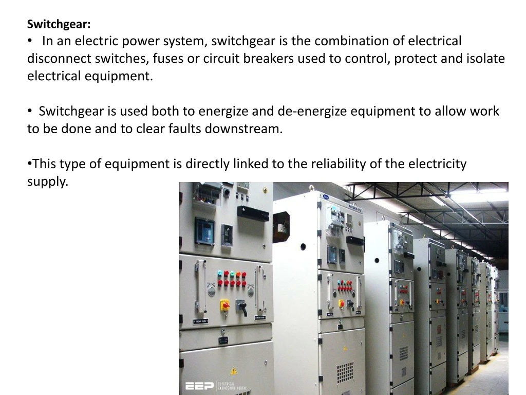
Switchgear: • In an electric power system, switchgear is the combination of electrical disconnect switches, fuses or circuit breakers used to control, protect and isolate electrical equipment. • Switchgear is used both to energize and de-energize equipment to allow work to be done and to clear faults downstream. • This type of equipment is directly linked to the reliability of the electricity supply.
Fuse: • In electronics and electrical engineering, a fuse is an electrical safety device that operates to provide over current protection of an electrical circuit. • Its essential component is a metal wire or strip that melts when too much current flows through it, thereby interrupting the current • The fuse element is made of zinc, copper, silver, aluminum, or alloys to provide stable and predictable characteristics. • Fuses have been used as essential safety devices from the early days of electrical engineering. Today there are thousands of different fuse designs which have specific current and voltage ratings, breaking capacity and response times, depending on the application. • The time and current operating characteristics of fuses are chosen to provide adequate protection without needless interruption.
Circuit Breaker: • A circuit breaker is an automatically operated electrical switch designed to protect an electrical circuit from damage caused by excess current from an overload or short circuit. • Its basic function is to interrupt current flow after a fault is detected. Unlike a fuse, which operates once and then must be replaced, a circuit breaker can be reset (either manually or automatically) to resume normal operation
Switch Fuse Unit (SFU): • The Rewirable Switch Fuse Units are used for distributing power and protecting electrical devices and cables from damage due to fluctuations. This fuse unit is housed in an enclosure made using quality CR steel sheet. The fuse units are stringently tested in compliance with the IS: 10027 and IS: 13947 part 1 and 3. • Salient Features • Cold Rolled steel sheet enclosure deep drawn for 16 to 63 Amp and fabricated for 100 & 200 Amp. • High conductivity due to nickel or silver plated contact • Durable and rewirable
The MCB has some advantages compared to fuse. • It automatically switches off the electrical circuit during abnormal condition of the network means in over load condition as well as faulty condition. • Another advantage is, as the switch operating knob comes at its off position during tripping, the faulty zone of the electrical circuit can easily be identified. But in case of fuse, fuse wire should be checked by opening fuse grip or cutout from fuse base, for confirming the blow of fuse wire. • Quick restoration of supply can not be possible in case of fuse as because fuses have to be rewirable or replaced for restoring the supply. But in the case of MCB, quick restoration is possible by just switching on operation. • Handling MCB is more electrically safe than fuse. Because of to many advantages of MCB over fuse units, in modern low voltage electrical network, miniature circuit breaker is mostly used instead of backdated fuse unit. • Only one disadvantage of MCB over fuse is that this system is more costlier than fuse unit system.
Working Principle Miniature Circuit Breaker • There are two arrangement of operation of miniature circuit breaker. • One due to thermal effect of over current and • Other due to electromagnetic effect of over current. • The thermal operation of miniature circuit breaker is achieved with a bimetallic strip whenever continuous over current flows through MCB, the bimetallic strip is heated and deflects by bending. This deflection of bimetallic strip releases mechanical latch. As this mechanical latch is attached with operating mechanism, it causes to open the miniature circuit breaker contacts. • But during short circuit condition, sudden rising of current, causes electromechanical displacement of plunger associated with tripping coil or solenoid of MCB. The plunger strikes the trip lever causing immediate release of latch mechanism consequently open the circuit breaker contacts. This was a simple explanation of miniature circuit breaker working principle.
If circuit is overloaded for long time, the bi - metallic strip becomes over heated and deformed. This deformation of bi metallic strip causes, displacement of latch point. The moving contact of the MCB is so arranged by means of spring pressure, with this latch point, that a little displacement of latch causes, release of spring and makes the moving contact to move for opening the MCB. The current coil or trip coil is placed such a manner, that during short circuit fault the mmf of that coil causes its plunger to hit the same latch point and make the latch to be displaced. Hence the MCB will open in same manner. Again when operating lever of the miniature circuit breaker is operated by hand, that means when we make the MCB at off position manually, the same latch point is displaced as a result moving contact separated from fixed contact in same manner. So, whatever may be the operating mechanism, that means, may be due to deformation of bi - metallic strip, due to increased mmf of trip coil or may due to manual operation, actually the same latch point is displaced and same deformed spring is released, which ultimately responsible for movement of the moving contact. When the the moving contact separated from fixed contact, there may be a high chance of arc. This arc then goes up through the arc runner and enters into arc splitters and is finally quenched. When we switch on an MCB, we actually reset the displaced operating latch to its previous on position and make the MCB ready for another switch off or trip operation.
Miniature Circuit Breaker Construction • Frame of Miniature Circuit Breaker • Operating Mechanism of Miniature Circuit Breaker • Trip Unit of Miniature Circuit Breaker • Operation of Miniature Circuit Breaker • There are three mechanisms provided in a single miniature circuit breaker to make it switched off. If we carefully observe the picture beside, we will find there are mainly one bi - metallic strip, one trip coil and one hand operated on-off lever. Electric current carrying path of a miniature circuit breaker shown in the picture is like follows. First left hand side power terminal - then bimetallic strip - then current coil or trip coil - then moving contact - then fixed contact and - lastly right had side power terminal. All are arranged in series.
Molded Case Circuit Breaker Definition and Function • A molded case circuit breaker, abbreviated MCCB, is a type of electrical protection device that can be used for a wide range of voltages, and frequencies of both 50 Hz and 60 Hz. The main distinctions between molded-case and miniature circuit breaker are that the MCCB can have current ratings of up to 2,500 amperes, and its trip settings are normally adjustable. An additional difference is that MCCBs tend to be much larger than MCBs. As with most types of circuit breakers, an MCCB has three main functions: • Protection against overload – currents above the rated value that last longer than what is normal for the application. • Protection against electrical faults – During a fault such as a short circuit or line fault, there are extremely high currents that must be interrupted immediately. • Switching a circuit on and off – This is a less common function of circuit breakers, but they can be used for that purpose if there isn’t an adequate manual switch.
Molded case circuit breakers can have very high current ratings, which allows them to be used in heavy duty applications. The following are some typical uses of an MCCB: • Main electric feeder protection • Capacitor bank protection • Generator protection • Welding applications • Low current applications that require adjustable trip settings • Motor protection
ELCB (Earth Leakage Circuit Breaker): An ECLB is one kind of safety device used for installing an electrical device with high earth impedance to avoid shock. These devices identify small stray voltages of the electrical device on the metal enclosures and intrude the circuit if a dangerous voltage is identified. The main purpose of Earth leakage circuit breaker (ECLB) is to stop damage to humans & animals due to electric shock. • There are two types of Earth Leakage Circuit Breaker (ELCB) • Voltage Operated ELCB • Current Operated ELCB
The terms "wire" and "cable" are sometimes used interchangeably, but they're not quite the same thing. A wire is a conductor that carries a single current, while a cable is two or more conductors. There are many different types of cable, with varying electric power cable specifications.
Rod Earthing A copper rod of 12.5mm (1/2 inch) diameter or 16mm (0.6in) diameter of galvanized steel or hollow section 25mm (1inch) of GI pipe of length above 2.5m (8.2 ft) are buried upright in the earth manually or with the help of a pneumatic hammer.
Strip or Wire Earthing: In this method of earthing, strip electrodes of cross-section not less than 25mm x 1.6mm (1in x 0.06in) is buried in a horizontal trenches of a minimum depth of 0.5m. If copper with a cross-section of 25mm x 4mm (1in x 0.15in) is used and a dimension of 3.0mm2 if it’s a galvanized iron or steel. This type of earthing is employed where the soil is rocky and soil digging is difficult.
Pipe Earthing: 1.Domestic ,distribution Substations 2.A galvonised steel /cast iron pipe of length of 2.5m should be driven into ground such that top edge of the rod is at 1.25m from earth surface
Plate Earthing: Major substations and generating stations In plate earthing system, a plate made up of either copper with dimensions 60cm x 60cm x 3.18mm (i.e. 2ft x 2ft x 1/8 in) or galvanized iron (GI) of dimensions 60cm x 60cm x 6.35 mm (2ft x 2ft x ¼ in) is buried vertical in the earth (earth pit) The plate is at the depth of 1.5mfrom the ground level.
Cables/Wires 1.According to the conductor material used: i)Copper conductor wires ii)Aluminium Conductor Wires
Cables/Wires 2.According to the number of cores i)Single core cable ii)Double core cable iii)Three core cable iV)Four core cable v)Three and half core cable
Cable/Wires • Three core cables are normally used for balanced loads (L1, L2 and L3). • A four core cable would be used for loads where a neutral is required (L1, L2, L3 and N). • Often the neutral will carry significantly less current than the line conductors (in a balanced system it should be zero) and a half sized neutral is used to save copper (three and a half cores).
Cables/Wires 3.According to voltage grading i)Low tension Cable –Upto 1000V ii)High tension Cable –Upto11KV iii)Super tension Cable (11KV-33KV) iv) Extra High tension Cable (33KV-132KV) v)Extra Super Tesion Cable(>132KV) 4.According to type of insulation
Cables/Wires 4.According to type of Insulation i)Vulcanized Indian Rubber(VIR)insulated wires/Cables ii)TRS(Tough Rubber Sheathed) iii)PVC(Polyvinyl Chloride cables) iv)Lead Sheathed cables v)Weather proof cables vi)Flexible cords and cables
Cables/Wires 5.According to the Type of Construction • Belted Cable • H Type Cable • S.L.Type Cable • HSL Type Cable
Types of Batteries • Primary Batteries • Secondary Batteries
Secondary Batteries • Lead Acid • Nickel Cadmium(NiCd) • Lithium Ion(Li Ion)
Lead Acid Battery • Working of Lead Acid Battery
Nickle-Cadmium Battery The active materials in a Nickle-Cadmium Battery * *Nickel Hydroxide Ni(OH)2 acts as the positive plate * The spongy Cadmium (Cd) acts as the negative plate. * Although the electrolyte does not enter into chemical reaction with plates or any other chemical, it is made up of Potassium Hydroxide (KOH) solution with specific gravity of 1.2.
Nickle-Cadmium Battery • Electrical Characteristics: • The average EMF of Nickle-Cadmium battery is 1.2 V per cell. However, the EMF of a cell can go as high as up to 1.4 v , when the cell is fully charged.
Lithium-ion battery • Lithium-ion batteries are incredibly popular these days. • You can find them in laptops, PDAs, cell phones and iPods. • Most energetic rechargeable batteries available.