Download
1 / 45
450 likes | 554 Views
MERIS US Workshop 14 July 2008. MERIS Level 2 processing Ludovic Bourg. Presentation Outlook. PART 1: MERIS L2 PROCESSING GENERAL OVERVIEW Common Processing Cloud Branch Land Branch Water Branch PART 2: WATER BRANCH ALGORITHMS, A MORE DETAILED DESCRIPTION Atmosphere correction

E N D
MERIS US Workshop14 July 2008 MERIS Level 2 processing Ludovic Bourg
Presentation Outlook • PART 1: MERIS L2 PROCESSING GENERAL OVERVIEW • Common Processing • Cloud Branch • Land Branch • Water Branch • PART 2: WATER BRANCH ALGORITHMS, A MORE DETAILED DESCRIPTION • Atmosphere correction • Ocean Color • PART 3: TOWARD VICARIOUS ADJUSTMENT OF MERIS TOA REFLECTANCE (at Level 2)
MERIS LEVEL 2 PROCESSINGPART 1 MERIS L2 PROCESSING GENERAL OVERVIEW
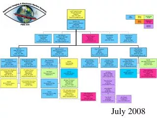
Functionnal breakdown ATBDs available on the web at: http://envisat.esa.int/instruments/meris/atbd/ (Some under revision) • MERIS ESL: • Institutes: • FUB • GKSS • JRC • LISE/ULCO • LOV • PML • Companies: • ACRI • BC
Pre-processing • For all pixels: • Interpolate all annotations at pixel • Derive surface pressure from ECMWF mean sea level and pixel altitude • For valid pixels only: • convert L1b radiance L into TOA reflectance r
Pressure processing From • measurement within the O2-A absorption line at 761 nm (band 11) and reference at 753 nm (band 10) • accurate knowledge of the band 11 central wavelength • Cloud Top Pressure (neural net) • Surface Pressure (polynomials) • Derived at every valid pixel (input to classification) • Valid product only over relevant surface types (cloud and land pixels, respectively)
Pixel identification • Goal: sort valid pixels into Cloud, Water and Land • Means: • Cloud screening: • spectrum values & slopes (on Rayleigh corrected reflectance) • pressure tests • Land/water discrimination: • A priori land/water classification • radiometric (clear sky) land/water reclassification where a priori is questionable (on gas corrected reflectance)
Smile Correction • “Smile”: in-FOV variation of channels central wavelength • Can affect Level 2 products if not accounted for • Need for a simple and robust smile correction • First order correction • Restricted to Land and Water pixels • Restricted to surface dependent subset of bands • Based on surface dependent spectral slope estimates
Cloud branch • Compute the cloud albedo, cloud optical thickness, cloud typeproducts (in addition to already available cloud top pressure) • Albedo and optical thickness are derived from polynomials of LTOA(753) using geometry and surface albedo dependant coefficients. Polynomial coefficients are derived from radiative transfer simulations. • Cloud type product is an index computed from CTP and CA (defined by ISCCP climatology project)
Total Column Water Vapour • Determine column water vapour content above all surfaces from absorption at 900 nm • Polynomials of T=LTOA(900)/LTOA(885) (from RT simulations) • Surface dependent algorithms • Above land and water with high glint: • Correct for surface reflectance and its spectral dependency, estimated from LT at 753, 885, 900 • Account for surface pressure (vertical profile) • Above water, no/low glint : • Correct T for aerosol estimated from LT at 779, 865 • Above cloud : • Account for cloud optical thickness (a MERIS cloud product) • Account for underlying surface albedo
Land branch MERISGlobal Vegetation Index Atmosphere Corrections over Land MERISTerrestrial Chlorophyll Index
Land branch • Atmosphere & geometry insensitive vegetation index • Remove unwanted pixels flags • Based on normalisedrTOA(B,R,IR) ( anisotropic) • Computes rectified rR for R & IR ( top of canopy at ref geometry) • Computes MGVI(rR(R), rR(IR))( FAPAR) MERIS Global Vegetation Index Atmosphere Corrections over Land MERIS Terrestrial Chlorophyll Index
compute top of aerosol rtop(all pixels) • Retrieve aerosol over vegetation • select DDV pixels using ARVI • biome climatology & models rS at 3 bands • find best aerosol model a and t443 so that {rS}(3 bands) propagated to TOA match measures Land branch MERIS Global Vegetation Index Atmosphere Corrections over Land MERIS Terrestrial Chlorophyll Index
Remove unwanted pixels flags • Based on rTOP(R, IR1,IR2) • MTCI Land branch MERIS Global Vegetation Index Atmosphere Corrections over Land MERIS Terrestrial Chlorophyll Index
Water confidence checks Turbid water screening and atmosphere correction Clear water atmosphere correction Ocean color processing Water branch
High and medium glint flags • Glint correction • Whitecaps flag • High inland water flag • Ice, haze, high aerosol flag Water branch Water confidence checks Turbid water screening and atmosphere correction Clear water atmosphere correction Ocean color processing
Identify bright waters (sediment dominated case 2, CASE2_S flag) • Estimate sediment load • Estimate IR marine signal rw Water branch Water confidence checks Turbid water screening and atmosphere correction Clear water atmosphere correction Ocean color processing
Identify aerosol: t865, aNIR (from IR where rw known) • Estimate atmosphere path reflectance including molecular/aerosol coupling • Provide rw(all b but 761 & 900) • Flags: quality and science Water branch Water confidence checks Turbid water screening and atmosphere correction Clear water atmosphere correction Ocean color processing
From rw, provide: • Algal 1 (case 1) • Algal 2, TSM, YS (case 2) • Instantaneous Photosynthetically Available Radiation (PAR) Water branch Water confidence checks Turbid water screening and atmosphere correction Clear water atmosphere correction Ocean color processing
MERIS LEVEL 2 PROCESSINGPART 2 A MORE DETAILED DESCRIPTION OF WATER BRANCH ALGORITHMS
Gas correction (O3, H2O, O2) • Pixels screening & glint • Coupled molecules/aerosols correction • directional water leaving reflectance Water Processing: more details • Input: top of atmosphere reflectance • Mains steps: • Atmosphere correction • Ocean color processing • Chl 1 from band ratio (case 1) • Chl 2, TSM, YS from Neural network (case 2)
[stratospheric aerosol layer] ozone layer (absorption) O2, H2O (absorption coupled with scattering) Cloud Air + aerosol mixture Air-water interface Water processing: atmosphere model
Sun Satellite absorption by gas molecules scattering by air molecules scattering + absorption by aerosol particles reflection at air/water interface scattering + absorption by water Water processing: simplified signal model
Water Processing: gas correction Gas corrections • O3: transmittance tO3 from ECMWF ozone and optical thickness for each band • H2O: transmittance at any band tH2O(b) estimated from measured tH2O(900) • O2: transmittance at any band tO2(b) estimated from measured tO2(761)
Water Processing: glint & bright pixels Pixels screening & glint flagging/correction: • Glint reflectance estimates: Cox & Munk anisotropic model (revised with Ebushi & al parameters, and fed by ECMWF wind vectors) • 2 glint thresholds and flags: • high glint: to high for reliable correction (rG≥a.r(865)) • medium glint: correction is required and possible(e ≤ rG < a.r(865)) rGC(l) = rng(l) – t. rG • “Bright pixels” screening: undetected clouds, haze, high aerosols and ice flagged (from a reflectance test at 412) • Whitecaps: raise flag upon wind speed, no correction
Water Processing: path reflectance • Based on a classical “black ocean in the NIR” approach • Using standard aerosol models closed to SeaWiFS ones • With some specificities: • Rayleigh/aerosol coupling accounted for through the use of rpath/rR (ATBD 2.7) • Extension to (moderately) sediment loaded waters through estimation of t.rw in the NIR (ATBD 2.6) • Additional aerosols with steep spectral dependency • Detection of absorbing aerosols using “deficit of reflectance at 560 nm” (ATBD 2.7) and corresponding additional models (Moulin et al)
Water Processing: turbid waters Purpose: To identify waters with significant backscatter in the NIR To provide corresponding reflectance estimates allowing atmosphere corrections
Water Processing: turbid waters • Simplified atmospheric model :single scattering approximation rrc = rGC-rR so that rrc-trw= ra t = diffuse transmission up & down, Rayleigh only • Find n and TSMthat explain rRCat 709, 779 & 865 • Realized using a simplified rw model • Ends up with t.rw estimates at 779, 865 + CASE2_S flag (ATBD 2.6 under revision)
Water Processing: aerosol identification Principle: • Inputs: rpath=rGC -t.rw at 779 and 865 (=rGC in case 1) • Tabulated relationships: • rpath/rR=f(t,l,W,model), (1) • t=f -1(rpath/rR,l,W,model) (2) • t(l,model) = t(lref,model) (3) • For all aerosol models: • Measured rpath/rRat 865 gives t865 using (2) • t865 gives t779 using (3) • t779 gives rpath/rRat 779using (1) • Select pair of models most closely bracketing measured rpath/rRat 779 and mixing ratio that fits.
Water Processing: aerosol identification Illustration with a set of 4 maritime models rpath/rR θs = 40°, θv = 30°, Δφ = π/2.
Water Processing: aerosol identification Global procedure: • identification done over the whole set of non-absorbing aerosols (MAR, COA, RUR with various RH + 3 “blue”) • best pair is selected, derive: at 510 nm • If not CASE2_S then: • Get rw(510) using • If rw< (mean+s)climatology repeat procedure with the absorbing aerosol families new candidate pairs • Select the one that minimizes |rw - (mean+s)climatology| • Proceed to correction at all bands
Water Processing: aerosol products • Aerosol optical thickness at 865nm • Aerosol Angstrom exponent (779-865) • Atmosphere correction flags: • validity flag for aerosol products • OADB (out of aerosol database: limited representativity) • ABSO_D: absorbing aerosols were selected • CASE2_S: significant scattering by water in the NIR • Medium glint • High glint • Ice/haze/high aerosol
Water Processing: Ocean Color Ocean color products: • Algal 1 index (~Chla concentration, mg.m-3): case 1 • Algal 2 index (~Chla concentration, mg.m-3): case 2 • Total Suspended matter (g.m-3): case 2 • Yellow Substance (absorption at 442, m-1): case 2 • Flags: • Validity flags for each product • CASE2_Anomalous: excess of reflectance at 560 as compared to derived Algal1 anomalous scattering
Water Processing: Algal 1 • In Case 1 water, • R(l) is a function of algal pigments • R(442)/R(560) (or R(490)/R(560)) is directly related with Chl Eu : upwelling irradiance (integral of radiance) just below the surface Ed : downwelling irradiance bi-directional distribution of the upwelling radiance (depends on Chl) contribution of the air-water interface From MERIS case 1 model:
Water Processing: Algal 1 • Reflectance correction for bi-directionality requires knowledge of Chl iterative method: • Select highest ratio among bi{443,490,520}, bref=560 • Normalization of rw ratio using tabulated f/Q (Chl dependent) • log Chl1 = polynomial (band_ratio) Iterative process
Water Processing: Case 2 Neural Network • Case 2 waters: • Described by optical components: • Phytoplankton pigment absorption apig • Absorption of all other substances ayp(dissolved Gelbstoff y and non-algal particles p) • Scattering of all particles bp • Global inversion is done using a Neural Network (NN), provides apig(442), ayp(442), bp(442) from reflectance in 8 bands • NN is trained offline over a large data set produced by Radiative Transfer model • Internal consistency verification with a forward model NN • Components converted to concentrations using reversible relationships
* Water Processing: Case 2 Neural Network *: 412 to 709, excluding 681
Water Processing: Case 2 Neural Network • Neural Net principle and training conditions are described in a recent publication: • Doerffer, R. and Schiller H. (2007) ’The MERIS Case 2 water algorithm’, Internal Journal of Remote Sensing, 28:3, 517-535 • As well as: • MERIS ATBD 2.12 (under revision) • MERIS Reference Model Document (under revision)
MERIS LEVEL 2 PROCESSINGPART 3 TOWARD VICARIOUS ADJUSTMENT OF MERIS TOA REFLECTANCE
Vicarious Adjustment: Principle • Based on the work currently led at NASA for SeaWiFS and MODIS vicarious calibration, see Franz et al. 2007, Bailey et al. 2007. • Consist in computing averaged multiplicative gain factors to correct the “TOA signal”, thanks to a DB of reference in-situ rtw • “TOA signal” = Level 2 reflectance pre-corrected for smile, gaseous absorption, glint, i.e. at input of the Water AC algorithm • rgcnew(l) = rgc(l)*G(l) for l in the VIS and NIR • Two-step approach separating the NIR and VIS channels, avoiding iterative procedure within the AC algorithm • First adjust one of the two NIR bands used in aerosol retrieval (the other one assumed perfect) G(779) for MERIS AC • AC being now assumed “perfect”, adjust all other bands G(l) • The methodology fully imbricates the sensor response and the processing: • The gains need to be updated each time a change occur in the processing (LUT, algorithm, L1b calibration, etc…) • A strong effort of traceability in the gain computation, with respect to all other processing parameters, should be maintained.
Vicarious Adjustment: Principle • Computation starts from the decomposition: rgc(l) = rpath(l) + td(l) . rw(l) • Knowing the true (or targeted) signal through in-situ measurements, individual gains are computed matchup per matchup by • gi(l) = [rtpath(l) + ttd(l) . rtw(l)] / [rpath(l) + td(l) . rw(l)] • Average gains are finally derived: G(l) = mean(gi(l)) • To calibrate the NIR, one requires: • the most NIR band (865) is perfectly calibrated ( assumption), • rw(lNIR) is truly negligible, ( oligotrophic sites) • aerosol spectral dependency is known ( specific sites). • Thus one has • rtgc(865) = rgc(865) = rpath(865) • rtgc(779) = gi(779).rgc(779) = rtpath(779) • Using provides rtpath(779) hence gi(779) • Once NIR is calibrated, rtpath(l)=rpath(l) and ttd(l)=td(l) at all bands, hence gi(l)
Vicarious Adjustment: implementation • NIR calibration sites: South Pacific Gyre and South Indian Ocean, selected model MAR 90% (including continental background in the free troposphere and H2SO4 in the stratosphere of fixed t550 = 0.025 and 0.005 resp.) • In-situ data: AAOT, BOUSSOLE and MOBY (foreseen : NOMAD) • Data selection: • no flags within 25x25 px • Results in: • NIR (2003 & 2007 only): • 14 at SPG • 34 at SIO • VIS: • 28 at MOBY • 29 at BOUSOLE • 3 at AAOT
Vicarious Adjustment: Preliminary Results MERIS SeaWiFS SeaWiFS figure fromBailey S.W., S.B. Hooker, D. Antoine, B.A. Franz, P.J. Werdell, « Sources and assumptions for the vicarious calibration of ocean color satellite observations », Applied Optics, 47(12), 2035-2045.
INTER-SENSOR COMPARISONS: CHLa MERIS:no vicarious adjustment • Source GlobColour, • Courtesy: • SeaWiFS: NASA (v5.2) • MODIS: NASA (v1.1) • MERIS: ESA (v2.0Q)