Download
1 / 20
200 likes | 363 Views
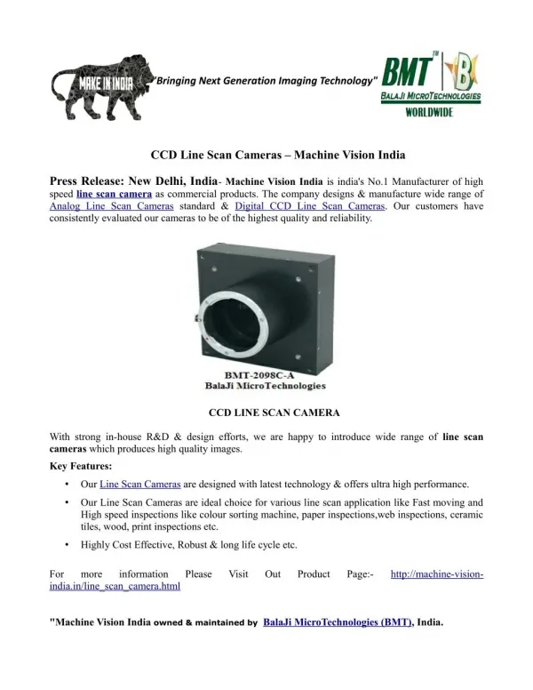
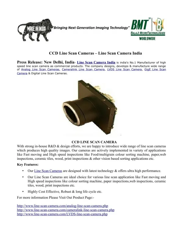
Machine vision,Line Scan Camera,Analog Line Scan Camera,Analog Line Scan Cameras,Vision Camera<br>2098 PIXEL RGB LINE SCAN CAMERA | KLI-2113 LINE SCAN CAMERAS<br>We offer high speed 2098 RGB CCD line Scan Camera suitable for colour sorter, surface inspection, defect identification, Machine Vision & textile applications<br>http://www.line-scan-camera.com/analog-line-scan-camera.php<br><br>

E N D
Tri-Linear Series: BMT-2098C-A User Manual Tri-Linear Series: BMT-2098C-A User Manual Colour Line Scan Analog Camera BalaJi MicroTechnologies Pvt. Ltd. (A Unit of B.B. Group of Companies) Corporate Headquarter: New Delhi, India Sales/business Operation: D-2/20, Sector-10 | DLF Faridabad-121006 | Haryana, INDIA Tel # +91-129-4006203 | +91-129-6561300 Email (For Overseas Sales): sales.overseas@balaji-microtechnologies.com Email (For India Sales): sales.india@balaji-microtechnologies.com Website: http://www.balaji-microtechnologies.com/ 2014-15 Copyright BalaJi MicroTechnologies Pvt. Ltd. Page 1
Tri-Linear Series: BMT-2098C-A User Manual Table of Contents 1. 5 INTRODUCTION 1.1 1.2 5 5 5 5 6 TYPICAL SPECIFICATION SAFETY MEASURE 1.2.1 1.2.2 1.2.3 Supply voltage Limitation Power Supply of camera Warranty 2. 7 ELECTRICAL & INTERFACE 2.1 7 7 8 9 9 9 CONNECTORS 2.1.1 2.1.2 2.1.3 2.1.4 2.1.5 Power & I/O Connector Analog & Digital BNC connector RS-232 connector RS-232 communication format Cables 3. 10 CAMERA FUNCTIONS AND CONTROL 3.1 3.2 3.3 10 11 12 12 13 13 14 17 17 SERIAL CAMERA CONFIGURATION INTERNAL & EXTERNAL CLOCK WORKING MODES OF CAMERA 3.3.1 3.3.2 3.3.3 3.4 3.5 3.6 Internal sync mode Integration time for internal sync mode External sync mode OUTPUT CLOCK DELAY CAMERA RESET & SAVE CONFIGURATION GAIN & OFFSET ADJUST 4. 19 MECHANICAL 5. 20 ORDERING CODE 2014-15 Copyright BalaJi MicroTechnologies Pvt. Ltd. Page 2
Tri-Linear Series: BMT-2098C-A User Manual List of Tables TABLE 1-CAMERA SPECIFICATIONS ......................................................................................................................................... 5 TABLE 2-LIMITS FOR SUPPLY VOLTAGE.................................................................................................................................... 5 TABLE 3 CONNECTOR INFORMATION ....................................................................................................................................... 7 TABLE 4POWER &I/OCONNECTOR ...................................................................................................................................... 8 TABLE 5-CAMERA COMMAND LIST ....................................................................................................................................... 10 TABLE 6CAMERA RETURN STRING ........................................................................................................................................ 11 2014-15 Copyright BalaJi MicroTechnologies Pvt. Ltd. Page 3
Tri-Linear Series: BMT-2098C-A User Manual List of Figures FIGURE 1CONNECTORS OF THE CAMERA ------------------------------------------------------------------------------------------------------------ 7 FIGURE 2POWER &I/O CONNECTOR --------------------------------------------------------------------------------------------------------------- 8 FIGURE 3RS-232PIN CONNECTION ----------------------------------------------------------------------------------------------------------------- 9 FIGURE 4DIGITAL OUTPUT SIGNAL OF THE CAMERA ---------------------------------------------------------------------------------------------- 11 FIGURE 5INTERNAL SYNC MODE ------------------------------------------------------------------------------------------------------------------- 12 FIGURE 6EXTERNAL SYNC MODE ------------------------------------------------------------------------------------------------------------------- 13 FIGURE 7SYNC OUTPUT VS.ANALOG OUTPUT --------------------------------------------------------------------------------------------------- 14 FIGURE 8CLKOUT DELAY VS.ANALOG OUTPUT (0T,0.25T,0.5T,0.75T) ------------------------------------------------------------------ 16 FIGURE 9GAIN AND OFFSET POTENTIOMETERS --------------------------------------------------------------------------------------------------- 17 FIGURE 10MECHANICAL DIMENSIONS OF CAMERA ----------------------------------------------------------------------------------------------- 19 2014-15 Copyright BalaJi MicroTechnologies Pvt. Ltd. Page 4
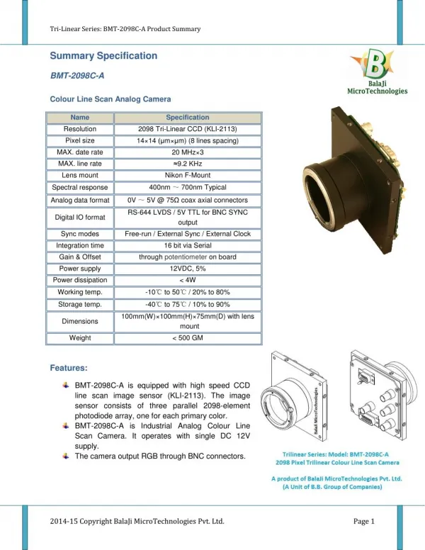
Tri-Linear Series: BMT-2098C-A User Manual 1. Introduction 1.1 Typical Specification Name Resolution Specification 2098 Tri-Linear CCD (KLI-2113) 14×14 (µm×µm) (8 lines spacing) Pixel size 20 MHz×3 ≈9.2 KHz MAX. date rate MAX. line rate Lens mount Spectral response Nikon F-Mount 400nm ~ 700nm Typical -10℃ to 50℃ / 20% to 80% 0V ~ 5V @ 75Ω coax axial connectors -40℃ to 75℃ / 10% to 90% Analog data format Digital IO format Sync modes Integration time Gain & Offset Power supply Power dissipation RS-644 LVDS / 5V TTL for BNC SYNC output Free-run / External Sync / External Clock 16 bit via Serial through potentiometer on board 12 VDC, 5% < 4W Working temp. Storage temp. 100mm(W)×100mm(H)×66.2mm(D) with lens mount < 500 GM Dimensions Weight Table 1-Camera Specifications 1.2 Safety Measure 1.2.1 Supply voltage Limitation MIN. TYP. 12V DC MAX. 12.6 V DC 11.4 V DC Table 2-Limits for Supply Voltage 1.2.2 Power Supply of camera Warning! • Check camera supply voltage before using the camera. ?Cut-off camera’s power supply before plug or un-plug and connectors. ?Do not reverse the polarity of the input power! Reversing the polarity of the input power can severely damage the camera and leave it non-operational. 2014-15 Copyright BalaJi MicroTechnologies Pvt. Ltd. Page 5
Tri-Linear Series: BMT-2098C-A User Manual Information! Without sufficient cooling, the camera can get hot enough during operation. Allow sufficient air circulation around the camera to prevent internal heat build-up in your system and to keep the camera housing temperature during operation below 50° C. Provide additional cooling such as fans or heat sinks if necessary. 1.2.3 Warranty ? Camera comes with 12 months warranty from the date of Invoice subject to following below terms. ? Do not remove any of the camera’s labels. If labels are removed, user accepts that the warranty of the camera is void. ? Read this Manual first before using the camera ? Keep foreign matter outside of the camera ? Do not open the housing. Touching internal components may damage them. Be careful not to allow liquids, flammable, or metallic material inside the camera housing. If operated with any foreign matter inside, the camera may fail or cause a fire. ?Electromagnetic fields: Do not operate the camera in the vicinity of strong electromagnetic fields. Avoid electrostatic charging. ?Transporting: Only transport the camera in its original packaging. Do not discard the packaging. ?Cleaning: Avoid cleaning the surface of the CCD sensor if possible. If you must clean it, use a soft, lint free cloth dampened with a small quantity of high quality window cleaner. Do not use ethylated alcohol. Because electrostatic discharge can damage the CCD sensor, you must use a cloth that will not generate electrostatic charge during cleaning (cotton is a good choice). ? To clean the surface of the camera housing, use a soft, dry cloth. To remove severe stains, use a soft cloth dampened with a small quantity of neutral detergent, then wipe dry. Do not use volatile solvents such as benzene and thinners; they can damage the surface finish of the camera. 2014-15 Copyright BalaJi MicroTechnologies Pvt. Ltd. Page 6
Tri-Linear Series: BMT-2098C-A User Manual 2. Electrical & Interface 2.1 Connectors 3 3 3 2 4 1 5 Figure 1 Connectors of the camera Notes 1 2 3 4 5 LED Status Power & I/O connector Analog BNC connector Digital BNC connector RS-232 connector Table 3 connector information 2.1.1 Power & I/O Connector 2014-15 Copyright BalaJi MicroTechnologies Pvt. Ltd. Page 7
Tri-Linear Series: BMT-2098C-A User Manual Figure 2 Power & I/O connector No. 1 2 3 4 5 6 7 8 Signal SHIELD VDD GND NC SYNC+ CLKOUT- SYNCIN+ CLKIN- Dir — — — — O O IN IN Function Shield +12V DC IN GND —— Sync Out + Clock Out - Sync Input + Clock Input - No. — 9 10 11 12 13 14 15 Signal — NC- GND NC SYNC- CLKOUT+ SYNCIN- CLKIN+ Dir — — — — O O IN IN Function GND Sync Out - Clock Out + Sync Input - Clock Input + Table 4 Power & I/O Connector Information! GNDs are connected together inside to the Digital Ground of the camera. NC should not be connected. Information! All IO signals (SYNC, SYNCIN, CLKOUT, CLKIN) are RS-644/LVDS standard. 2.1.2 Analog & Digital BNC connector There are total 4 standard BNC type connectors for analog & digital output ? 3 analog BNC connectors output Red/Green/Blue channel of CCD sensor signal with 0V-5V range ? The digital BNC output SYNC signal (same signal source with SYNC+/- RS-644) with 5V TTL format. 2014-15 Copyright BalaJi MicroTechnologies Pvt. Ltd. Page 8
Tri-Linear Series: BMT-2098C-A User Manual 2.1.3 RS-232 connector Figure 3 RS-232 Pin connection DB9/Male Connector Signal RXD TXD GND NC No. 2 3 5 Type RS-232 Receive Line RS-232 Transmit Line GND Not Connect 1,4,6,7,8,9 2.1.4 RS-232 communication format Duplex without handshaking. 9600 bauds, 8bit data, no parity bit, 1 stop bit. 2.1.5 Cables Information! Recommend using twisted pair cables for all RS-644/LVDS Input and output signals, for longer transfer distance, the cable should meet the RS-644 standard requirements. Information! All analog outputs should use 75Ω coax axial cables for best signal quality. 2014-15 Copyright BalaJi MicroTechnologies Pvt. Ltd. Page 9
Tri-Linear Series: BMT-2098C-A User Manual 3. Camera functions and control 3.1 Serial camera configuration Commands are based on ASCII protocol of the serial communication, the command syntax is: Command=Parameter(CR) Command: one or more characters continued with a “=” character. Parameter: must be one or more characters within “0” to “9”. (CR): :Represent the “Enter” character (Hex value is 0x0D), same for below. : : “Blanc” (or SPACE) character is not allowed in the command syntax. Setting Command Parameter Description Integration time setting, valid for Internal Sync only, default value is 0. Internal Clock + Internal Sync, default Internal Clock + External Sync External Clock + Internal Sync External Clock + External Sync 20MHz Pixel Clock, default 10MHz Pixel Clock 5MHz Pixel Clock 2.5MHz Pixel Clock No Delay, default ¼T Delay ½T Delay ¾T Delay Reset the camera logic Save current setting to memory, the setting will be restored after power up. Integration Time I= 0~65535 2 3 0 1 2 3 1 0 1 2 3 0 1 Working Modes M= Internal Clock Frequency F= Clock Delay D= Reset Logic T= Save Configuration W= 1 Table 5-Camera command list Return String Status Description Successful Operation Successful Blanc character detected, without “=” character, without command character(s) or parameter character(s). <OK>(CR) Error <ERR><Syntax Error!>(CR) <ERR><Invalid Command!>(CR) Error Unknown Command Error There are one or more of character is not <ERR><Invalid 2014-15 Copyright BalaJi MicroTechnologies Pvt. Ltd. Page 10
Tri-Linear Series: BMT-2098C-A User Manual Parameter!>(CR) within the “0” to “9” range Parameter is out of setting range Error <ERR><Out of Range!>(CR) <ERR><Function Not Support!>(CR) <ERR><Internal Error!><ERR=n>(CR) Error Setting a function that camera not support Error Internal Errors Table 6 Camera return string 3.2 Internal & external clock The camera could be set to use internal or external clock source. The output digital signal SYNC & CLOCKOUT should be like the figure below: Figure 4 Digital output signal of the camera With internal clock setting, user could also set 4 different CLKOUT frequencies: Setting F=0 F=1 F=2 F=3 CLKOUT Frequency 20MHz 10MHz 5MHz 2.5MHz T Value 50ns 100ns 200ns 400ns The camera also accept user input external clock to drive the CCD as desired frequency, note the input via CLKIN RS-644 input CLOCKIN frequency should be 4 times of the CLKOUT frequency you want to set, for example, if you need 2MHz of CLKOUT frequency, then the input clock frequency to the CLKIN input should be 8 MHz. Signal CLOCKIN CLKOUT Description MIN. 4MHz 1MHz TYP. —— —— MAX. 80MHz 20MHz External input clock frequency Pixel clock rate 2014-15 Copyright BalaJi MicroTechnologies Pvt. Ltd. Page 11
Tri-Linear Series: BMT-2098C-A User Manual Information! Recommend using twisted pair cables for all RS-644/LVDS Input and Output signals, for longer transfer distance, the cable should be meet the RS-644 standard requirements. 3.3 Working modes of camera 3.3.1 Internal sync mode Figure 5 Internal sync mode With internal sync setting (both for internal clock or external clock), the integration is controlled by camera’s internal logic module, integration time could be set via “I” command. 2014-15 Copyright BalaJi MicroTechnologies Pvt. Ltd. Page 12
Tri-Linear Series: BMT-2098C-A User Manual 3.3.2 Integration time for internal sync mode For internal sync mode, integration time could be set via the “I” command, the actual integration time and line rate could be calculated using formula below: Integration Time = ?2170 + ?? × 16?? × T ?ns? 10? Line Rate = Integration Time ?Hz? Where I=value set via “I” command (value range is 0 – 65535), and T=pixel clock period according to the internal of external clock setting. When using the internal clock with maximum 20 MHz pixel clock rate, the maximum and minimum line rate is: 10? Line Rate???= 108500≈ 9216 ?Hz? 10? Line Rate???= 52536500≈ 19 ?Hz? 3.3.3 External sync mode For external sync mode setting, integration time will be controlled by the external input SYNC signal, and the internal integration setting via “I” command would be invalid in this mode. Figure 6 External sync mode 2014-15 Copyright BalaJi MicroTechnologies Pvt. Ltd. Page 13
Tri-Linear Series: BMT-2098C-A User Manual External SYNCIN signal should be a period pulse, the positive edge would trigger the internal integration control, and the SYNCIN period should be satisfying the formula below: SYNCIN Period ?Integration Time? ≧ 2172 × T ?ns? 3.4 Output clock delay Due to the nature of CCD sensor, the output signal is not a regular continues analog signal, with each pixel reset for output register inside the CCD sensor, the output is a pulse like analog signal similar as figure below: Figure 7 SYNC output vs. Analog output This will need the clock output sample the right position of the analog output. The pixel output clock rate and the cable both will cause delay of the analog signals, so the camera could be set four step delay of the CLKOUT signal to obtain best sample position. 2014-15 Copyright BalaJi MicroTechnologies Pvt. Ltd. Page 14
Tri-Linear Series: BMT-2098C-A User Manual Users could use the “D” command to set the delay, from 0T to 0.75T with 0.25T step, below is the acquired image from the camera to explain the delay function (For the demo below, the 0.5T setting is the best position): 2014-15 Copyright BalaJi MicroTechnologies Pvt. Ltd. Page 15
Tri-Linear Series: BMT-2098C-A User Manual Figure 8 CLKOUT delay vs. Analog output (0T, 0.25T, 0.5T, 0.75T) 2014-15 Copyright BalaJi MicroTechnologies Pvt. Ltd. Page 16
Tri-Linear Series: BMT-2098C-A User Manual 3.5 Camera reset & save configuration Using “T=1” command to perform a internal logic reset of the camera. Information! Recommend using reset command after changing the working mode or setting of internal clock frequency change. Using “W=1” command will store all current settings to internal memory, when the camera is power off and on again, the setting will automatic restore from the internal memory. 3.6 Gain & offset adjust The camera has total 6 of potentiometers, 2 of each is pair for adjusting gain and offset of each color channel, please refer to below image for the position of each potentiometer. Figure 9 Gain and offset potentiometers Potentiometer Direction ↻ ↺ Description Increase Gain (More sensitivity) Gain Decrease Gain (Less sensitivity) 2014-15 Copyright BalaJi MicroTechnologies Pvt. Ltd. Page 17
Tri-Linear Series: BMT-2098C-A User Manual ↻ ↺ Lower Offset (More black) Offset Higher Offset (More white) Information! Default gain is setting to the lowest. Information! Increase the gain will also increase the noise of the camera output, but the total noise to signal (dB) ratio will not change apparently. 2014-15 Copyright BalaJi MicroTechnologies Pvt. Ltd. Page 18
Tri-Linear Series: BMT-2098C-A User Manual 4. Mechanical UNIT: mm Figure 10 Mechanical dimensions of camera Warning The lens should be Mount after removing the protection caps of the camera to avoid dust onto CCD’s optic window. 2014-15 Copyright BalaJi MicroTechnologies Pvt. Ltd. Page 19
Tri-Linear Series: BMT-2098C-A User Manual 5. Ordering code Model Number BMT-2098C-A BMT-2098M-A Description 2098 Pixel CCD Colour Line Scan Camera 2098 Pixel CCD Monochrome Line Scan Camera For more product information or inquiry, please contact BalaJi MicroTechnologies Pvt. Ltd. (A Unit of B.B. Group of Companies) Corporate Headquarter: New Delhi, India Sales/business Operation: D-2/20, Sector-10 | DLF Faridabad-121006 | Haryana, INDIA Tel # +91-129-4006203 | +91-129-6561300 Email (For Overseas Sales): sales.overseas@balaji-microtechnologies.com Email(For India Sales): sales.india@balaji-microtechnologies.com Website: http://www.balaji-microtechnologies.com/ BalaJi MicroTechnologies Page 20