Download
1 / 20
200 likes | 206 Views
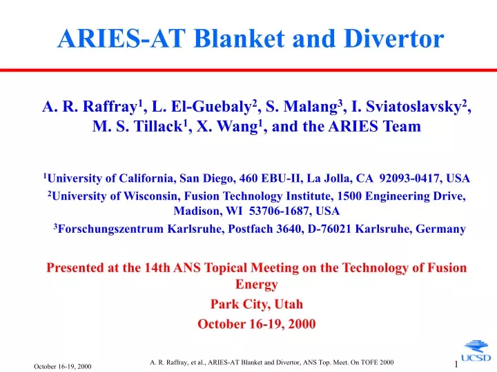
ARIES-AT Blanket and Divertor. A. R. Raffray 1 , L. El-Guebaly 2 , S. Malang 3 , I. Sviatoslavsky 2 , M. S. Tillack 1 , X. Wang 1 , and the ARIES Team 1 University of California, San Diego, 460 EBU-II, La Jolla, CA 92093-0417, USA

E N D
ARIES-AT Blanket and Divertor A. R. Raffray1, L. El-Guebaly2, S. Malang3, I. Sviatoslavsky2, M. S. Tillack1, X. Wang1, and the ARIES Team 1University of California, San Diego, 460 EBU-II, La Jolla, CA 92093-0417, USA 2University of Wisconsin, Fusion Technology Institute, 1500 Engineering Drive, Madison, WI 53706-1687, USA 3Forschungszentrum Karlsruhe, Postfach 3640, D-76021 Karlsruhe, Germany Presented at the 14th ANS Topical Meeting on the Technology of Fusion Energy Park City, Utah October 16-19, 2000 A. R. Raffray, et al., ARIES-AT Blanket and Divertor, ANS Top. Meet. On TOFE 2000
Presentation Highlights How Design Was Developed to Meet Overall Objective Overall Objective Develop ARIES-AT Blanket and Divertor Designs to Achieve High Performance while Maintaining: • Attractive safety features • Simple design geometry • Reasonable design margins as an indication of reliability • Credible maintenance and fabrication processes Design Utilizes High-Temperature Pb-17Li as Breeder and Coolant and SiCf/SiC Composite as Structural Material Outline • Power Cycle • Material • ARIES-AT Reactor • Blanket Design and Analysis • Divertor Design and Analysis • Fabrication • Conclusions A. R. Raffray, et al., ARIES-AT Blanket and Divertor, ANS Top. Meet. On TOFE 2000
Maximize potential gain from high-temperature operation with SiCf/SiC Compatible with liquid metal blanket through use of IHX High efficiency translates in lower COE and lower heat load Brayton Cycle Offers Best Near-Term Possibility of Power Conversion with High Efficiency* • Min. He Temp. in cycle = 35°C • 3-stage compression with 2 inter-coolers • Turbine efficiency = 0.93 • Compressor efficiency = 0.88 • Recuperator effectiveness = 0.96 • Cycle He fractional DP = 0.03 Max. Cycle He Temperature = 1050°C Cycle efficiency = 0.585 *R. Schleicher, A. R. Raffray, C. P. Wong, "An Assessment of the Brayton Cycle for High Performance Power Plant," 14th ANS Top. Meet. On TOFE A. R. Raffray, et al., ARIES-AT Blanket and Divertor, ANS Top. Meet. On TOFE 2000
SiCf/SiC Enables High Temperature Operation and its Low Decay Heat Helps Accommodate LOCA and LOFA Events W/O Serious Consequences on In-Reactor Structure1,2 Properties Used for Design Analysis Consistent with Suggestions from International Town Meeting on SiCf/SiC Held at Oak Ridge National Laboratory in Jan. 20003 • Density ≈ 3200 kg/m3 • Density Factor 0.95 • Young's Modulus ≈ 200-300 GPa • Poisson's ratio 0.16-0.18 • Thermal Expansion Coefficient 4 ppm/°C • Thermal Conductivity in Plane ≈ 20 W/m-K • Therm. Conductivity through Thickness ≈ 20 W/m-K • Maximum Allowable Combined Stress ≈ 190 MPa • Maximum Allowable Operating Temperature ≈ 1000 °C • Max. Allowable SiC/LiPb Interface Temperature ≈ 1000°C • Maximum Allowable SiC Burnup ≈ 3%* 1D. Henderson, et al, and the ARIES Team, ”Activation, Decay Heat, and Waste Disposal Analyses for ARIES-AT Power Plant," 2E. Mogahed, et al, and the ARIES Team, ”Loss of Coolant and Loss of Flow Analyses for ARIES-AT Power Plant," 14th ANS T. M. On TOFE 3See: http://aries.ucsd.edu/PUBLIC/SiCSiC/, also A. R. Raffray, et al., “Design Material Issues for SiCf/SiC-Based Fusion Power Cores,” submitted to Fusion Engineering & Design, August 2000 * From ARIES-I A. R. Raffray, et al., ARIES-AT Blanket and Divertor, ANS Top. Meet. On TOFE 2000
ARIES-AT Machine and Power Parameters1,2 Power and Neutronics3 Parameters Fusion Power 1719 MW Neutron Power 1375 MW Alpha Power 344 MW Current Drive Power 25 MW Overall Energy Multiplicat. 1.1 Tritium Breeding Ratio 1.1 Total Thermal Power 1897 MW Ave. FW Surf. Heat Flux 0.26 MW/m2 Max. FW Surf. Heat 0.34 MW/m2 Average Wall Load 3.2 MW/m2 Maximum O/B Wall Load 4.8 MW/m2 Maximum I/B Wall Load 3.1 MW/m2 Machine Geometry Major Radius 5.2 m Minor Radius 1.3 m FW Location at O/B Midplane 6.5 m FW Location at Lower O/B 4.9 m I/B FW Location 3.9 m Toroidal Magnetic Field On-axis Magnetic Field 5.9 T Magnetic Field at I/B FW 7.9 T Magnetic Field at O/B FW 4.7 T 1F. Najmabadi, et al.and the ARIES Team, “Impact of Advanced Technologies on Fusion Power Plant Characteristics,” 14th ANS Top. M.on TOFE 2R. L. Miller and the ARIES Team, “Systems Context of the ARIES-AT Conceptual Fusion Power Plant,” 14th ANS Top. Meet. On TOFE 3L. A. El-Guebaly and the ARIES Team, “Nuclear Performance Assessment for ARIES-AT Power Plant,” 14th ANS Top. Meet. On TOFE A. R. Raffray, et al., ARIES-AT Blanket and Divertor, ANS Top. Meet. On TOFE 2000
Cross-Section and Plan View of ARIES-AT Showing Power Core Components A. R. Raffray, et al., ARIES-AT Blanket and Divertor, ANS Top. Meet. On TOFE 2000
ARIES-AT Blanket Utilizes a 2-Pass Coolant Approach to Uncouple Structure Temperature from Outlet Coolant Temperature ARIES-AT Outboard Blanket Segment Configuration Maintain blanket SiCf/SiC temperature (~1000°C) < Pb-17Li outlet temperature (~1100°C) A. R. Raffray, et al., ARIES-AT Blanket and Divertor, ANS Top. Meet. On TOFE 2000
Poloidal Distribution of Surface Heat Flux and Neutron Wall Load A. R. Raffray, et al., ARIES-AT Blanket and Divertor, ANS Top. Meet. On TOFE 2000
Moving Coordinate Analysis to Obtain Pb-17Li Temperature Distribution in ARIES-AT First Wall Channel and Inner Channel • Assume MHD-flow-laminarization effect • Use plasma heat flux poloidal profile • Use volumetric heat generation poloidal and radial profiles • Iterate for consistent boundary conditions for heat flux between Pb-17Li inner channel zone and first wall zone • Calibration with ANSYS 2-D results A. R. Raffray, et al., ARIES-AT Blanket and Divertor, ANS Top. Meet. On TOFE 2000
Temperature Distribution in ARIES-AT Blanket Based on Moving Coordinate Analysis Max. SiC/PbLi Interf. Temp. = 994 °C Pb-17Li Outlet Temp. = 1100 °C Pb-17Li Inlet Temp. = 764 °C • Pb-17Li Inlet Temp. = 764 °C • Pb-17Li Outlet Temp. = 1100 °C • From Plasma Side: - CVD SiC Thickness = 1 mm - SiCf/SiC Thickness = 4 mm (SiCf/SiC k = 20 W/m-K) - Pb-17Li Channel Thick. = 4 mm - SiC/SiC Separ. Wall Thick. = 5 mm (SiCf/SiC k = 6 W/m-K) • Pb-17Li Vel. in FW Channel= 4.2 m/s • Pb-17Li Vel. in Inner Chan. = 0.1 m/s • Plasma heat flux profile assuming no radiation from divertor FW Max. CVD and SiC/SiC Temp. = 1009°C° and 996°C° A. R. Raffray, et al., ARIES-AT Blanket and Divertor, ANS Top. Meet. On TOFE 2000
Detailed Stress Analysis of Blanket Module to Maintain Conservative Margins as Reliability Measure e.g. Stress Analysis of Outboard Module • 6 modules per outboard segment • Side walls of all inner modules are pressure balanced except for outer modules which must be reinforced to accommodate the Pb- 17Li pressure (1 MPa) • For a 2-cm thick outer module side wall, the maximum pressure stress = 85 MPa • The side wall can be tapered radially to reduce the SiC volume fraction and benefit tritium breeding while maintaining a uniform stress • The thermal stress at this location is small and the sum of the pressure and thermal stresses is << 190 MPa • The maximum pressure stress + thermal stress at the first wall ~60+113 MPa. A. R. Raffray, et al., ARIES-AT Blanket and Divertor, ANS Top. Meet. On TOFE 2000
Reference Divertor Design Utilizes Pb-17Li as Coolant Outboard Divertor Plate • Single power core cooling system • Low pressure and pumping power • Analysis indicates that proposed configuration can accommodate a maximum heat flux of ~5-6 MW/m2 • Alternate Options - He-Cooled Tungsten Porous Heat Exchanger (ARIES-ST) - Liquid Wall (Sn-Li) Outlet Pb-17LiManifold SiCf/SiC Poloidal Channels Tungsten Armor Inlet Pb-17LiManifold A. R. Raffray, et al., ARIES-AT Blanket and Divertor, ANS Top. Meet. On TOFE 2000
ARIES-AT Divertor Configuration and Pb-17Li Cooling Scheme Accommodating MHD Effects: • Minimize Interaction Parameter (<1) (Strong Inertial Effects) • Flow in High Heat Flux Region Parallel to Magnetic Field (Toroidal) • Minimize Flow Length and Residence Time • Heat Transfer Analysis Based on MHD-Laminarized Flow A. R. Raffray, et al., ARIES-AT Blanket and Divertor, ANS Top. Meet. On TOFE 2000
Temperature Distribution in Outer Divertor PFC Channel Assuming MHD-Laminarized LiPb Flow • 2-D Moving Coordinate Analysis • Inlet temperature = 653°C • W thickness = 3 mm • SiCf/ SiC Thickness = 0.5 mm • Pb-17Li Channel Thickness = 2 mm • SiCf/SiC Inner Wall Thick. = 0.5 mm • LiPb Velocity = 0.35 m/s • Surface Heat Flux = 5 MW/m2 Max. W Temp. = 1150°C Max. SiCf/ SiC Temp. = 970°C A. R. Raffray, et al., ARIES-AT Blanket and Divertor, ANS Top. Meet. On TOFE 2000
Divertor Channel Geometry Optimized for Acceptable Stress and Pressure Drop • 2-cm toroidal dimension and 2.5 mm minimum W thickness selected (+ 1mm sacrificial layer) • SiCf/SiC thermal pressure stress ~ 160+30 MPa • DP minimized to ~0.55/0.7 MPa for lower/upper divertor Pressure Stress Thermal Stress A. R. Raffray, et al., ARIES-AT Blanket and Divertor, ANS Top. Meet. On TOFE 2000
Develop Plausible Fabrication Procedures and Minimize Joints in High Irradiation Region E.g. First Outboard Region Blanket Segment 1. Manufacture separate halves of the SiCf/SiC poloidal module by SiCf weaving and SiC Chemical Vapor Infiltration (CVI) or polymer process; 2. Manufacture curved section of inner shell in one piece by SiCf weaving and SiC Chemical Vapor Infiltration (CVI) or polymer process; 3. Slide each outer shell half over the free-floating inner shell; 4. Braze the two half outer shells together at the midplane; 5. Insert short straight sections of inner shell at each end; Brazing procedure selected for reliable joint contact area A. R. Raffray, et al., ARIES-AT Blanket and Divertor, ANS Top. Meet. On TOFE 2000
ARIES-AT First Outboard Region Blanket Segment Fabrication Procedure (cont.) 6. Form a segment by brazing six modules together (this is a bond which is not in contact with the coolant; and 7. Braze caps at upper end and annular manifold connections at lower end of the segment. A. R. Raffray, et al., ARIES-AT Blanket and Divertor, ANS Top. Meet. On TOFE 2000
Maintenance Methods Allow for End-of-Life Replacement of Individual Components* * L. M. Waganer, “Comparing Maintenance Approaches for Tokamak Fusion Power Plants,” 14th ANS Topical Meeting on TOFE A. R. Raffray, et al., ARIES-AT Blanket and Divertor, ANS Top. Meet. On TOFE 2000
Blanket Outboard Region 1 No. of Segments 32 No. of Modules per Segment 6 Module Poloidal Dimension 6.8 m Avg. Module Toroidal Dimen. 0.19 m FW SiC/SiC Thickness 4 mm FW CVD SiC Thickness 1 mm FW Annular Channel Thickness 4 mm Avg. LiPb Velocity in FW 4.2 m/s FW Channel Re 3.9 x 10⁵ FW Channel Transverse Ha 4340 MHD Turbulent Transition Re 2.2 x 10⁶ FW MHD Pressure Drop 0.19 MPa Maximum SiC/SiC Temp. 996°C Maximum CVD SiC Temp. (°C) 1009 °C Max. LiPb/SiC Interface Temp. 994°C Avg. LiPb Vel. in Inner Channel 0.11 m/s Divertor Poloidal Dimension (Outer/Inner) 1.5/1.0 m Divertor Channel Toroidal Pitch 2.1 cm Divertor Channel Radial Dimension 3.2 cm No. of Divertor Channels (Outer/Inner) 1316/1167 SiC/Si Plasma-Side Thickness 0.5 mm W Thickness 3.5 mm PFC Channel Thickness 2 mm Number of Toroidal Passes 2 Outer Div. PFC Channel V (Lower/Upper) 0.35/0.42 m/s LiPb Inlet Temperature (Outer/Inner) 653/719 °C Pressure Drop (Lower/Upper) 0.55/0.7 MPa Max. SiC/SiC Temp. (Lower/Upper) 970/950°C Maximum W Temp. (Lower/Upper) 1145/1125°C W Pressure + Thermal Stress ~35+50 MPa SiC/SiC Pressure + Thermal Stress ~35+160 MPa Toroidal Dimension of Inlet and Outlet Slot 1 mm Vel. in Inlet & Outlet Slot to PFC Channel 0.9-1.8 m/s Interaction Parameter in Inlet/Outlet Slot 0.46-0.73 Typical Blanket and Divertor Parameters for Design Point A. R. Raffray, et al., ARIES-AT Blanket and Divertor, ANS Top. Meet. On TOFE 2000
Conclusions • ARIES-AT Blanket and Divertor Design Based on High-Temperature Pb-17Li as Breeder and Coolant and SiCf/SiC Composite as Structural Material • High performance • Attractive safety features • Simple design geometry • Reasonable design margins as an indication of reliability • Credible maintenance and fabrication processes • Key R&D Issues • SiCf/SiC fabrication/joining, and material properties at high temperature and under irradiation including: • Thermal conductivity, maximum temperature, lifetime • MHD effects in particular for the divertor A. R. Raffray, et al., ARIES-AT Blanket and Divertor, ANS Top. Meet. On TOFE 2000