Download
1 / 37
370 likes | 496 Views
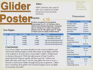
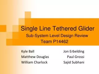
Single Line Tethered Glider. Sub-System Level Design Review. Team P14462. Kyle Ball Matthew Douglas William Charlock. Jon Erbelding Paul Grossi Sajid Subhani. Team Introduction. Agenda. Project Description Review Engineering Requirements Review Functional Decomposition Review

E N D
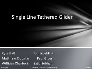
Single Line Tethered Glider Sub-System Level Design Review Team P14462 Kyle Ball Matthew Douglas William Charlock Jon Erbelding Paul Grossi Sajid Subhani
Agenda • Project Description Review • Engineering Requirements Review • Functional Decomposition Review • Top 3 Concepts from Last Review • Concept Feasibility • Glider Analysis and Feasibility • Base Station Analysis and Feasibility • Project Planning • Work Breakdown Structure
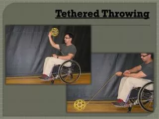
Project Description Review • Goal: Design, build, and test a tethered, small-scale, human-controlled glider. • Critical Project Objectives: • Maintain maximum tension on the tether • Sustaining horizontal and vertical flight paths • Measure and record tether tension and position • Understand the influential parameters for sustained, tethered, unpowered flight Glider Tether Base Station Operator w/ controller
Review of Top 3 System Concepts IMU with Single Axis Load Cell 3 Single Axis Load Cell 2 Potentiometers with Single Axis Load Cell
Choosing the Glider Bixler v1.1 EPO Foam Phoenix 2000 EPO Foam Wing span: 2 [m] Chord length: 0.3 [m] Mass: 0.98 [kg] Front mounted propeller Reinforced • Wing span: 1.4 [m] • Chord length: 0.2 [m] • Mass: 0.65 [kg] • Middle mounted propeller • Only EPO Foam
Choosing the Glider The smaller Bixler glider creates less tension for a larger operating range Able to operate with an affordable load cell
Flight Analysis Wind Speed: ~ 11 mph
Flight Analysis Wind Speed: ~ 22 mph
Flight Analysis Wind Speed: ~ 44 mph
Qualitative DOE • Slower wind speed: lower tension • Larger flight path radius: lower tension • Beta angle peaks: ~ 94-95° • Tension peaks: ~ 20 [m] tether length • Tension must be less than 5000 [N] (1100 lbs)
Quantitative DOE • Choosing flight configuration • Inputs • Maximum allowable tension • Observed wind speed • Outputs • Beta angle • Tether length • Flight path radius
Bridle and Tether Setup Use a tension of 3000 lbs as an overestimate. Maximum allowable stress for Bixler glider: 30 MPa Bridle attached at two points on the fuselage causes structural failure at the wing root with 180 MPa
Ideal Bridle Location Analysis Optimum tether location: 0.51 m from root. Optimum tether angle: 54 deg from airplane
Wing Stress Analysis • Maximum stress: 15 MPa
3 Single-Axis Load Cells • Created 3-D model of the system in SolidWorks • Works well when the ball joints are kept in tension as seen in Fig 1. • Ball joints fail when they are put into compression as seen in Fig 2. Fig. 2 Fig. 1
Base Station Equipment Phidgets 3140_0 – S Type Load Cell Bourns 3540S-1-103L Potentiometer
Work Breakdown Structure (10-12) • Paul: • Jon: • Kyle: • Matt: • Saj: • Bill: