Download
1 / 35
350 likes | 449 Views
Single Line Tethered Glider. System Level Design Review. Team P14462. Kyle Ball Matthew Douglas William Charlock. Jon Erbelding Paul Grossi Sajid Subhani. Team Introduction. Agenda. Project Description Review Customer Needs Review Customer Requirements Review

E N D
Single Line Tethered Glider System Level Design Review Team P14462 Kyle Ball Matthew Douglas William Charlock Jon Erbelding Paul Grossi Sajid Subhani
Agenda • Project Description Review • Customer Needs Review • Customer Requirements Review • Functional Decomposition • Concept Development • Concept Comparison • Data Collection Architecture • Risk Assessment • Project Planning • Work Breakdown Structure
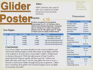
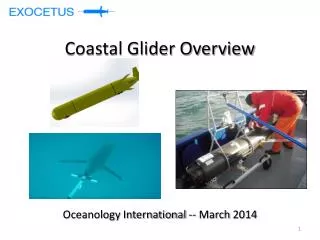
Project Description • Goal: Design, build, and test a tethered, small-scale, human-controlled glider. • Critical Project Objectives: • Maintain maximum tension on the tether • Sustaining horizontal and vertical flight paths • Measure and record tether tension and position • Understand the influential parameters for sustained, tethered, unpowered flight Glider Tether Base Station Operator w/ controller
Engineering Requirements Yellow: Major design Biege: DAQ Grey: Test flight White: System environment
Concept Development • Gliders • Buy an RC glider • Design and build an RC glider • Measurement Devices on Base Station • Buy a 3-axis Load Cell • Build Load Cell from three 1-axis Load Cells • GPS with Force Gauge • Resistance Gyro with Force Gauge • IMU with 1-axis Load Cell
Art’s Plane • Sustained multiple damages • Gained crash experience • Possible tethered flight concept tests • Salvage parts • Sorry Art
Buy Glider Pros: • Pre-Engineered to Fly • Can purchase spare parts • Fast shipping • Modifiable Cons: • Not guaranteed to fly with tether • Expensive • Limited modifications
Benchmarking (Buy) Bixler 2 Sky Eye Airwing WingSurfer Phoenix 2000
Build Glider Pros: • Can optimize plane for tethered flight • Build spare sparts • Resources available Cons: • Not guaranteed to fly • Requires time to build • Complex • Hard to balance • Could become expensive if mistakes are made
Benchmarking (Build) • Experimental Airlines tutorials (Photon Model as baseline) • Custom/interchangable design (wing, fuselage, rudder, etc.) • ~$80 - $100 (~50%-70% “1 time cost”)
Force Gauge and Resistance Gyro Pros: • Innovative Cons: • Expensive • Complex Data • Internal Turbulence • Requires current line on tether • Difficult to calibrate • Difficult to set up
3 Single-Axis Load Cells Pros: • Can repair individual components • Accurate • Cheap Components Cons: • Difficult to calibrate • Potential for noisy data
3-Axis Load Cell Pros: • Accurate • Precalibrated • Intuitive Setup Cons: • Expensive
IMU Board and 1-Axis Load Cell Pros: • Provides accurate position and orientation data Cons: • Requires noise filtering • Difficult to calibrate • IMU system would be on glider
Force Gauge and GPS Pros: • Digital Data • Accurate force measure Cons: • Expensive • GPS on glider changes weight • Difficult to calibrate • Difficult to set up • Innacurate position
2 Potentiometers and 1-Axis Load Cell Pros • Inexpensive • Accurate angles Cons • Easily breakable • Require precise machining
Top 3 System Concepts IMU with Single Axis Load Cell 3 Single Axis Load Cell 2 Potentiometers with Single Axis Load Cell
Data Collection Architecture • Data acquisition: LabVIEW or Arduino • Storage: SD Card or Laptop Data Collection Requirements:
Preliminary Budget Outline Purchase Price ($) Glider Glider 100 Receiver 60 Battery x2 40 Base Station Materials 100 Electronics 100 Total 400 Remaining (For Mistakes and Repairs) 100
Work Breakdown Structure • Paul: Glider Dynamics & IMU Implementation • Jon: Glider Dynamics & Load Cell Implementation • Kyle: EDGE & Load Cell Implementation / Base Station Construction • Matt: Glider Dynamics, Purchased Gliders Analysis & Potentiometer Implementation • Saj: DOE Research & Team Management • Bill: Built Glider Analysis & DAQ