Download

1 / 13
130 likes | 212 Views
SCT Endcap Module Initial Alignments Using Survey Data. Paul S Miyagawa University of Manchester. Outline. Objectives Available survey data Calculation of alignment constants Comparison with CSC constants Summary and future work. Objectives.

E N D
SCT Endcap Module Initial Alignments Using Survey Data Paul S Miyagawa University of Manchester
Outline • Objectives • Available survey data • Calculation of alignment constants • Comparison with CSC constants • Summary and future work ATLAS Software & Computing Workshop
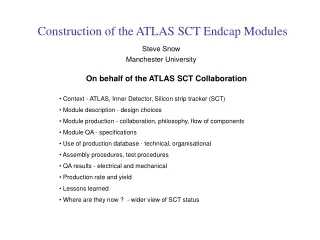
Objectives • Extensive survey data available for SCT endcap modules and discs • Combine the survey data to produce “as-built” module-on-disc (level-3) alignments • Compare with the distributions used for CSC production • Use alignments as initial step in alignment algorithms ATLAS Software & Computing Workshop
Module Survey Data (1) • Modules consist of two (or four) wafers mounted at an angle of 40 mrad • (For outer and middle modules, each wafer is split into two parts) • Hole and slot used to mount the module on disc ATLAS Software & Computing Workshop
Module Survey Data (2) • Modules surveyed during assembly at Manchester, NIKHEF and Geneva • Survey information on positions of wafers, hole + slot, angle between wafers • Uncertainties in module construction < O(10 μm) ATLAS Software & Computing Workshop
Disc Survey Data (1) • Modules mounted on disc in three rings • 40 modules each in inner and middle rings, 52 in outer ring • Outer and inner rings mounted on front face of disc, middle ring on rear face • At each position on disc, main/secondary pins insert into hole/slot on module • 2 reference holes define survey coordinates • Holes also used to align discs within the endcap ATLAS Software & Computing Workshop
Disc Survey Data (2) • Discs surveyed during assembly at Liverpool and NIKHEF • Positions of pins and reference holes surveyed on disc • Uncertainties in pin positions O(60 μm) • Should be dominant over module uncertainties ATLAS Software & Computing Workshop
Y x y z X Z Athena Conventions • Level-3 AlignableTrans-forms define translations and rotations of modules in local frame • Centre of rotations taken to be stereo centre on rφ face of module • Strips of rφ face point along radial direction • Strips of stereo face rotated 40 mrad • Transforms are for entire module; not available separately for each face of a module • Cannot reflect shift of stereo centre or non-nominal angle between wafers ATLAS Software & Computing Workshop
Stereo Centre of Module • Stereo centre defined to be intersection of central strips of each wafer • Shift in wafer positions relative to each other causes shift in stereo centre • Positions of overlaps relative to stereo centre are unaffected • Endpoints of strips relative to stereo centre are changed • Leads to inefficiency at one end of strips • Cannot be reflected by AlignableTransforms ATLAS Software & Computing Workshop
Angle Between Wafers • Central axis of module chosen such that angle between wafers is symmetric about nominal angle • Non-nominal angle affects positions of overlaps • Cannot be reflected by AlignableTransforms ATLAS Software & Computing Workshop
Alignment Parameters • Calculated in-plane translations and rotations for modules • Translations < O(100 μm) • Rotations O(400 mrad) • Distributions are (vaguely) Gaussian • Largely determined by positions of pins on disc • Still need to complete verification of data • Using Michal Dwuznik’s viewer • Running alignment algorithm on this set of misalignments ATLAS Software & Computing Workshop
Comparison with CSC Numbers • CSC misalignment set used flat distributions • estimates for CSC misalignments were slightly pessimistic • CSC misalignments are random; survey misalignments are correlated • Relative alignment between modules could be used as a constraint ATLAS Software & Computing Workshop
Summary and Future Work • Extensive survey data available for SCT endcap modules and discs • Uncertainties in module construction < O(10 μm) • Uncertainties in disc construction • Combined survey data to produce “as-built” in-plane level-3 alignments • Translations < O(100 μm) • Rotations O(400 mrad) • Roughly Gaussian distributions • Numbers used for CSC misalignments were slightly pessimistic • AlignableTransforms not available separately for each face of a module • Cannot reflect shift of stereo centre or non-nominal angle between wafers • Work to come • Complete verification of data • Compare reconstruction performance on real data with survey misalignments versus nominal geometry ATLAS Software & Computing Workshop