Download
1 / 27
270 likes | 395 Views
From the ATLAS SCT endcap module production to the commisionning. D. Ferrère, University of Geneva in behalf of the ATLAS SCT collaboration. Overview: Introduction of SCT The endcap modules and the specifications The module production and logistics

E N D
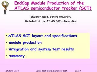
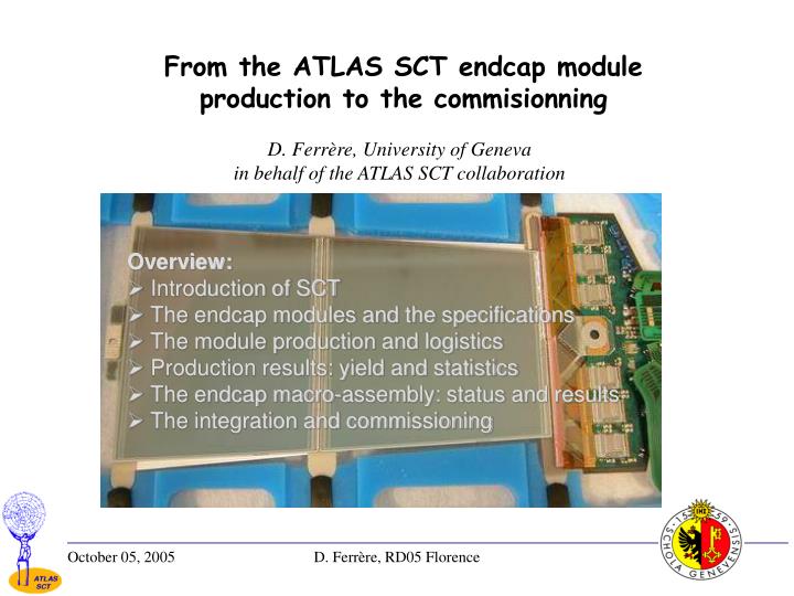
From the ATLAS SCT endcap module production to the commisionning D. Ferrère, University of Geneva in behalf of the ATLAS SCT collaboration • Overview: • Introduction of SCT • The endcap modules and the specifications • The module production and logistics • Production results: yield and statistics • The endcap macro-assembly: status and results • The integration and commissioning D. Ferrère, RD05 Florence
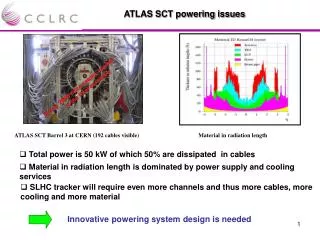
Atlas Experiment • Good tracking performances that are required for: • Secondary vertices • Impact parameters resolution • Track isolation • Measurement of high momentum particles Barrel Toroid Main physics motivation is the search for the Higgs boson, but not only given the large range of physics opportunities! Barrel Electromagnetic Calorimeter D. Ferrère, RD05 Florence
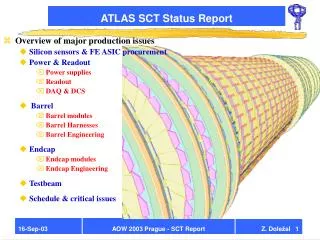
The SCT Semiconductor Tracker • SCT is made of 4088 modules: • ~ 61 m2 of silicon • 15,392 silicon wafers • ~ 6.3 million of readout channels Layout was done such that 4 space points can be reconstructed 5.6 m 1.04 m Endacp C: 9 wheels 1.53 m Endacp A: 9 wheels 4 barrels D. Ferrère, RD05 Florence
Middle short Endcap module types 1976 modules mounted on the 2 endcaps: 936 Outer Forward Modules 640 Middle Forward Modules (incl. 80 Short Middle) 400 Inner Forward Modules A module consists of 768 readout strips on each side with a constant angular pitch pointing towards the center of the wheel. Pitch between 70 to 90 m. D. Ferrère, RD05 Florence
Expanded view of an outer module 2 detectors strip-chained and readout at one end by 6 binary chips (ABCD3T) on each side 768 readout strips per side. Clock, control and signal are transmitted optically. Detectors are mounted back to back with a 20 mrad stereo angle. D. Ferrère, RD05 Florence
top side bottom side Module requirements • Electrical specifications: • (Based on a full set of digital/analog chip characterization + bias tests) • Noise occupancy at 1 fC less than 5x10⁻⁴ also related to the input noise • Less than 1 % dead channels ( 15/1536 ) – From the response curve test • Detector current less than 20 mA at 350V per detector. • Long Term Test (LTT) operation for 18-24 hours cold: • thermistor on hottest part of hybrid at ~10 ºC • Chip and detector biases and currents should remain stable D. Ferrère, RD05 Florence
13 XY alignment parameters 50 Z focus points for the module profile Module requirements • Mechanical specifications: • XY alignment - 13 parameters defined but critical are • Front-to-back detector alignment: midYF within ± 5 m • Individual detector angles: a1 to a4 within ± 130 mrad • Mounting hole and slot alignment: mhx, mhy and msy within ± 20 m • Z detector profile – 50 points are focused on the Si-detectors and per module side. None of them should exceed ± 115 m envelope. • Chip and fanins must be assembled within a defined envelope to avoid clashes with neighbor modules • The alignment and the profile must survive 10 thermal cycles between +35 ºC down to –30 ºC • Ceramic mounting surface should be clear of cracks (very fragile part) D. Ferrère, RD05 Florence
Cracow INP • Freiburg Univ. • CLRC, RAL • Freiburg Univ. • Geneva Univ. CERN • Manchester Univ. Liverpool, • Glasgow • MPI, Munich Prague Charles Univ, Prague Czech Tech. Univ. • Melbourne CERN • Nikhef • Valencia EndCap A macro-assembly Nikhef (NL) EndCap C macro-assembly Liverpool (UK) January 2006 March 2006 In progress ... ID Integration Tests and cosmic run CERN SR1 May/June 2006 ID Installation CERN ATLAS pit Module production and endcap flow diagram Hybrids (Cicorel + Freiburg) Fanin production (CNM Barcelona) Spine Production (Protvino) Spine QA & rework (CERN) Hybrid QA Site Complete Si-Detectors (Hamamatsu & CiS) Module Production and QA Cluster Others: Washers, glue D. Ferrère, RD05 Florence
Module assembly resources • - 7 assembly sites in total involving 12 institutes or Universities • Up to 6 technicians/site (~3 FTE) for the module assembly • Up to ~8 physicists and PhD per site (~2 FTE) for the module QA • Component selection and reception tests ~2h • Alignment and assembly of detectors ~2h + 24h glue curing • Detector current check and visual inspection ~40min • Assembly with hybrids and fanins ~1h30 + 24h glue curing • Wire bonding ~3h • Detector current check and visual inspection ~15min • Metrology survey ~30min • Thermal cycling ~18h • Metrology survey ~30min • Electrical characterization ~2h30 • Long Term Test electrical characterization ~24h • Inspection and packing for storage ~20min From start to the end a module fabrication takes ~9 working days/module! In practice a module is issued after 3 to 4 weeks! D. Ferrère, RD05 Florence
Assembly with spine Wire bonding Assembly with hybrid and fanins Module assembly procedure Detector alignment D. Ferrère, RD05 Florence
Endcap module production Production Started in June 03 and completed in May-June 05 Front side of an outer module Max production rate: ~55 modules/week Total : 2377 Outer : 1106 Middle : 775 Inner : 496 Number of modules were made with a 20% contingency to allow up to 15% lost at the production sites and 5% at the macro-assembly sites. Outer : 94.7% MidL : 94.4% MidS : 88.3% Inner : 87.4% Average yield : 93.1% D. Ferrère, RD05 Florence
Detector broken due to debris that was sticking on the backplane. This happened when sucking down on the miniature alignment stage. Module is broken! The spacer mounted on the spine was glued with an angle and clash during the assembly was unavoidable but impossible to anticipate. Module was aborted! Few illustrations of problems found – Part of the learning curve Teflon surface Detector scratches due to trapped debris into the teflon surface of the transfer plate. Module is out of detector current specs! Si surface D. Ferrère, RD05 Florence
Electrical QA results Good Out of specs Good Out of specs D. Ferrère, RD05 Florence
Mechanical QA results Some stats on essential XY alignment parameters Pass Good Good midyF specification inside ± 5 microns mhy specification inside ± 20 microns Good Stereo angle specification 20 ±0.13 mrad. Defined between front and back detector axis. D. Ferrère, RD05 Florence
Mechanical QA results ZminF Front and rear detector profile Pass Good Good D. Ferrère, RD05 Florence
Endcap macro-assembly Liverpool: Endcap C & Nikhef: Endcap A 40 middle modules Rear side 52 outer and 40 inner modules Front side Disk 5A in Module to Disk stand at NIKHEF D. Ferrère, RD05 Florence
Endcap C disk testing results (Liverpool) Average Input noise on the complete endcap C Outers : 1576e- Middles : 1529e- Inners : 1070e- Short Middles : 907e- Endcap A has similar results so far... D. Ferrère, RD05 Florence
Endcap C disk Thermal study (Liverpool) Tcoolant= -22 ºC, Tambient= -8 ºC Average±RMS: Hybrid main point: - 20.8 ± 0.8 ºC Detector-end temp: -18.5 ± 0.6 ºC (T. Jones) D. Ferrère, RD05 Florence
Endcap status EC-C cylinder with discs 6 to 9 at Liverpool • Endcap C (Liverpool): • Module to disc completed and tested • Discs 9 to 5 in cylinder • FSI to mount on discs 1 to 4 • Service to cylinder started: cooling, LMT, fibers, DCS • Delivery to CERN in January 06 EC-A Disk 8A inserted into cylinder at Nikhef • Endcap A (Nikhef): • Module to disc completed from 9 to 5 • Disks 9 to 7 in cylinder • Disk 5 under test • Modules to be mounted on disc 4 • Services to discs on disc 1 & 3 to do • Services to cylinder started: cooling, LMT, fibers, DCS • Delivery to CERN in March 06 D. Ferrère, RD05 Florence
Integration and commissioning at CERN SR1 • The 2 ECs will arrive at CERN in January 06 and March 06 • Reception tests: visual inspection, leak test and electrical tests • Final SCT assembly • Integration with TRT • Combined tests SCT/TRT - 9 SCT discs will be tested together on 1 sector • Installation into the pit foreseen in May and June 06 TRT trolley in aligned position for the integration Cantilever stand with 1 endcap D. Ferrère, RD05 Florence
Conclusions • SCT is one of the largest Si-Tracker (~61 m2). • A lot of expertise is essential from physicists, engineers and technicians in various fields such as: physics, mechanics, electronics, computing, thermodynamics,... • Even with the strict requirements, a module yield as high as 93.1% was achieved . 2377 modules have been built and 1976 will be used in SCT. • The EC module production was a great success and experience in all the assembly sites: 7 sites involving 12 universities and institutes. • Modules are completely mounted on discs for EC-C and half for EC-A and module performances are as expected! • The macro-assembly, service assembly, integration and commissioning are on the way or about to start at Liverpool, Nikhef and at CERN. • The installation into the pit is close: May 06 and June06. D. Ferrère, RD05 Florence
Extra slides D. Ferrère, RD05 Florence
Running conditions and features • 23 overlapping interactions every bunch crossing (at the full Luminosity) • A bunch-bunch crossing every 25ns (40MHz) • Maximum equivalent 1 MeV neutron fluence after 10 years is ~ 2.1014 n/cm2 • Operating temperature on silicon detectors is -7oC to contain the reverse annealing and the leakage current BUT the maintenance will likely require yearly warm-up of 2 days at 20oC and 2 weeks at 17oC • Operation in a 2 Tesla solenoid field • Material < 0.4 X0 at the outer SCT envelope • SCT coverage up to =2.5 • More than 99% hit efficiency is required D. Ferrère, RD05 Florence
Module components Hybrid: - 6 copper-kapton layers laminated onto a carbon-carbon substrate - Equipped with 12 ABCT3T readout chips and opto-chips for clock/control and readout • Detectors: • 5 detector types made in 4 inch wafers by 2 manufacturer (Hamamatsu and CiS) • 770 strips (1st and last not readout) of 20 micron width with an average pitch of ~80 mm • Fanins: • Aluminum strips on glass used for electrical connection and thermal isolation between hybrid and detectors. Different sets for the 3 module types. • 4 items per module: 2 left and 2 rights • Spine: • Made of TPG (Thermal Pyrolytic Graphite) for the excellent thermal conductivity and AlN ceramic pieces for the mechanical stiffness. All in one single item during the module assembly. • Location pads: • very precise hole and slot made on an Aluminium washer and glue onto FR4 piece. The slot washer is glued on the spine and the hole is overlapping the hybrid and the spine. D. Ferrère, RD05 Florence
Oracle DB (kernel 9i) SCT production Database • Why? • Traceability of the items, shipped items, assemblies and tests that had been made • Most of the relevant test data and parameters were stored in structured way otherwise stored in raw data • Useful GUI has been made either for upload or report thanks to: • Java applications for massive data upload • Web interfaces (SQL form) for individual data access or report • Java or other applications coupled with root display for statistics and reports • Encourages auto-discipline. Data transparent to all the collaboration and DB entries were one of the requirements to be qualified for the module production. D. Ferrère, RD05 Florence
Electrical QA results Long Term Test (LTT) After some stats decreased from 24h to 18h duration Very rare problems found with the modules (0.05%)! In principles problems are detected earlier during hybrid LTT. D. Ferrère, RD05 Florence
Endcap macro-assembly D. Ferrère, RD05 Florence