Download
1 / 41
420 likes | 596 Views
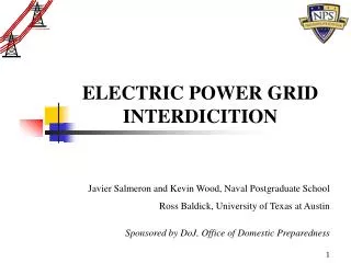
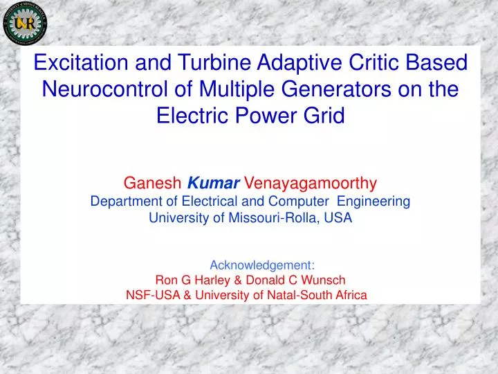
Excitation and Turbine Adaptive Critic Based Neurocontrol of Multiple Generators on the Electric Power Grid Ganesh Kumar Venayagamoorthy Department of Electrical and Computer Engineering University of Missouri-Rolla, USA Acknowledgement: Ron G Harley & Donald C Wunsch

E N D
Excitation and Turbine Adaptive Critic Based Neurocontrol of Multiple Generators on the Electric Power Grid Ganesh Kumar Venayagamoorthy Department of Electrical and Computer Engineering University of Missouri-Rolla, USA Acknowledgement: Ron G Harley & Donald C Wunsch NSF-USA & University of Natal-South Africa
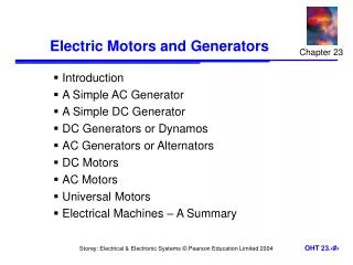
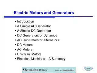
Electric Power System & its challenges Single Machine Power System Indirect Adaptive Control Approach Adaptive Critics Approach Results Multimachine Power System Adaptive Critics Approach Results Conclusions Presentation Outline
Electric Power Grid Loads M Busbars Lines Generators M
AREA 1 4 AREA 2 6 7 5 3 2 1 G1 G1 G2 11 G2 13 14 12 10 9 8 G1 G1 Load Load Load Load Qcap Qcap Qcap Qcap G2 AREA 4 G2 AREA 3 Multi-Machine Power System
AREA 1 4 AREA 2 6 7 5 3 2 1 G1 G1 G2 11 G2 13 14 12 10 9 8 G1 G1 Load Load Load Load Qcap Qcap Qcap Qcap G2 AREA 4 G2 AREA 3 Multi-Machine Power System
A Single Machine Infinite Bus System Governor Generator Line Pm Turbine VB VT Exciter Vfield Vref AVR VAVR PSS VPSS
Automatic voltage regulator and exciter combination AVR Exciter PID Compensation Micro-turbine and limits Governor Vref V fdm Pref V + entrained + ma Vt + + 1 K ( 1 sT )( 1 sT ) - av 1 Vfd reheater å v 1 v 2 steam servo motor + saturation + 1 sT å + + + 1 sT ( 1 sT )( 1 sT ) v 5 e V - v 3 v 4 + K ( 1 sT ) P - mi g g 1 + 1 1 ( 1 sFT ) Exciter å g 5 + + + 1 sT 1 sT 1 sT Input Filter Pm + 1 sT g 3 g 4 g 2 g 5 S e Micro-turbine and governor combination Saturation Conventional Controllers
A turbogenerator - nonlinear, non-stationary, fast acting, MIMO device, wide range of operating conditions and dynamic characteristics. Conventional AVRs, PSSs and turbine governors linearized power system model one operating point (OP). At any other Ops performance of the controllers degrades undesirable operating states. Conventional Controllers
Neural network based PSSs [OP Malik 1994, YM Park 1996] Inverse model fidelity of the model robustness is questionable Neural network based PSSs [KY Lee 1996] Indirect adaptive control – NN identifier and controller learning based on one time step error online learning required Tabu search and genetic algorithms for optimal PSS parameters [Abido 1999, 2000] Fuzzy logic PSSs [Malik] Venayagamoorthy – Indirect Adaptive Neural Network controller AVR and governor Online training Simulation and experimental [1999] Improving the Performance of Conventional AVR and Turbine Governor Controllers
Y(t)=[(t), Vt(t)] [(t), Vt(t)] Desired Ve, Pref D Response Turbogenerator B Predictor X(t+1) =[Vt(t+1), A M TDL TDL TDL A(t) Ve(t) (t+1)] Neuro- Pref(t) Error H C Controller E Neuro- K G ^ ^ Identifier ^ ^ I [(t+1), J Error Vt(t+1)] ^ ^ A(t) Adaptive Neurocontroller
Adaptive Critic Designs (ACDs) may be defined as designs that attempt to approximate dynamic programming in the general case. Dynamic Programming, in turn, is the only exact and efficient method for finding an optimal strategy of action over time in a noisy, nonlinear, non-stationary environment. The basic concept of all forms of dynamic programming can be illustrated as follows: Utility Function (U) Model of Reality (F) Dynamic Programming Secondary Utility (J) Adaptive Critic Designs based Controllers
Bellman’s equation of dynamic programming The cost of running true dynamic programming is proportional (or worse) to the number of possible states in the plant; that number, in turn, grows exponentially with the number of variables in the environment - ‘curse of dimensionality’ Therefore the need for approximate dynamic programming methods- ‘ACDS’ Dynamic Programming
Adaptive Critic Designs (ACDs) may be defined as designs that attempt to approximate dynamic programming in the general case. Critic & Action networks HDP CRITIC Y(t) J(t) DHP CRITIC Y(t) Adaptive Critic Designs
Model dependent Adaptive Critics Action dependent Adaptive Critics R(t+1) u(t) R(t) Model Critic Action J(t+1) u(t) R(t) J(t) Critic Action Forms of Adaptive Critic Designs
^ DY(t+1) U(t) J(t+1) ^ DY(t) CRITIC ^ TDL Plant DY(t-1) Target = J(t+1)+U(t) ACTION NETWORK CRITIC NETWORK 1 - J(t) + ^ TDL DY(t) Neuro- Identifier S ^ CRITIC Error DY(t-1) ^ DY(t-2) HDP Neurocontroller Designs • Action Network Learning • Critic Network Learning
DHP Critic Network Adaptation DHP critic networks learn minimization of the following error measure over all time steps, t
Yref PLANT Y(t) TDL ACTION Neural Network A(t) (t+1) MODEL Neural Network CRITIC Neural Network TDL TDL TDL + + + - - - EC2(t) MODEL Neural Network CRITIC Neural Network TDL TDL DHP Critic Network Adaptation
DHP Action Network Adaptation Yref = [Pref , Ve] PLANT Y(t) = [, Vt] TDL eA2(t) Y(t) + + ACTION Neural Network A(t) ^ TDL MODEL Neural Network CRITIC Neural Network ^ TDL ^ TDL Y(t), Y(t-1), Y(t-2)
A Single Machine Infinite Bus System Governor Generator Line Pm Turbine VB VT Exciter Vfield Vref AVR VAVR
Rotor Angle for a Temporary Short Circuit 75 70 DHP HDP 65 CONV 60 Rotor angle (degrees) 55 50 45 40 35 30 0 1 2 3 4 5 6 Time in seconds
Rotor Angle for a Temporary Short Circuit DHP HDP 80 COT CONV 75 70 Load angle in degrees 65 60 55 50 45 0 1 2 3 4 5 6 7 Time in seconds
Micro-Machine Research Laboratory at the University of Natal, Durban, South Africa
1 0.9 Terminal Voltage in pu 0.8 DHP 0.7 PSS + CONV CONV 0.6 0.5 10 11 12 13 14 15 16 17 18 19 20 Time in seconds 50 45 Load angle in degrees 40 DHP PSS + CONV 35 CONV 30 10 11 12 13 14 15 16 17 18 19 20 Time in seconds Rotor Angle for a Temporary Short Circuit
Multimachine Power System 1 4 7 1 S2 Governor 3 Micro #1 Pref1 G1 j0.5 0.01 j0.25 Pm1 0.012 j0.75 0.022 Micro-Turbine Pref1 Exciter S3 S1 VE1 1 Vpss + PSS 0.022 + Load Vt1 Infinite Bus Vref1 AVR j0.75 5 2 Governor 2 Micro #2 Pref2 6 G2 Pm2 0.012 j0.50 j0.25 Micro-Turbine 0.01 Exciter Pref2 VE2 AVR Vref2 Vt2
Micro-Machine Research Laboratory at the University of Natal, Durban, South Africa
Micro-Machine Research Laboratory at the University of Natal, Durban, South Africa December 2000/ January 2001
TCR & Exciter #1 TCR & Exciter #2 Generator #1 Generator #2 Micro- turbine #1 Micro- turbine #2 AVR and Turbine Governor #1 AVR and Turbine Governor #2 Generator #3 (Infinite Bus) Block Diagram of the Laboratory System Setup
M62/67 DSP Card • TMS320C6701- 32 bit floating point DSP • 15 times faster than any other single DSP • Expansion - two OMNIBUS I/O module cards • Allows for custom module designs • Plugs into a standard 32-bit PCI bus slot • Multiple cards may be installed in systems with full driver support under Windows 9x and NT
S1 Load Multimachine Power System 4 7 1 1 Pref1 S2 Micro #1 3 Pm1 G1 j0.5 0.01 j0.25 0.012 j0.75 0.022 Micro-Turbine Pref1 Exciter VE1 Ve1 + + Ve1 0.022 DHP Neurocontroller 1 Infinite Bus j0.75 5 Vt1 2 Governor Micro #2 2 Pref2 6 G2 Pm2 0.012 j0.50 j0.25 Micro-Turbine 0.01 Exciter Pref2 VE2 AVR Vref2 Vt2
Machine #1: Trans. Line Impedance Increase 1.01 1 Terminal voltage in pu 0.99 CONV_CONV 0.98 CONV_PSS_CONV 0.97 DHP_CONV 10 10.5 11 11.5 12 12.5 13 13.5 14 14.5 Time in seconds 40 35 Load angle in degrees CON_CONV 30 CONV_PSS_CONV 25 DHP_CONV 20 10 10.5 11 11.5 12 12.5 13 13.5 14 14.5 15 Time in seconds
Machine #2: Trans. Line Impedance Increase 40 35 Load angle in degrees CON_CONV CONV_PSS_CONV DHP_CONV 30 10 12 14 16 18 20 22 Time in seconds
Multimachine Power System 4 7 1 Pref1 S2 Micro #1 3 Pm1 G1 j0.5 0.01 j0.25 0.012 j0.75 0.022 Micro-Turbine Pref1 Exciter S1 VE1 Ve1 + + Ve1 Load 0.022 DHP Neurocontroller #1 1 Infinite Bus j0.75 5 Vt1 2 Pref2 Micro #2 Pm2 6 G2 0.012 j0.50 j0.25 Micro-Turbine Pref2 0.01 Exciter VE2 Ve2 + + Ve2 DHP Neurocontroller #2 2 Vt2
CONV__CONV CON_PSS_CON DHP_CONV DHP_DHP CONV_CONV CON_PSS_CONV DHP_CONV/DHP Machine # 2 & #1: Inductive Load Addition 45 40 35 Load angle in degrees 30 25 10 11 12 13 14 15 16 17 18 19 20 Time in seconds 50 45 40 35 Load angle in degrees 30 25 20 15 10 15 20 25 Time in seconds
CONV_CONV CON_PSS_CONV DHP_CONV/DHP Machine # 2 & #1: Trans. Line Impedance Increase 40 Load angle in degrees CONV__CONV 35 CON_PSS_CON DHP_CONV DHP_DHP 30 10 12 14 16 18 20 22 Time in seconds 40 35 Load angle in degrees 30 25 20 10 10.5 11 11.5 12 12.5 13 13.5 14 14.5 15 Time in seconds
CONV__CONV CON_PSS_CON DHP_CONV DHP_DHP CONV_CONV CON_PSS_CONV DHP_CONV/DHP Machine # 2 & #1: Short Circuit 50 45 Load angle in degrees 40 10 11 12 13 14 15 16 17 18 19 20 Time in seconds 50 45 Load angle in degrees 40 35 10 11 12 13 14 15 16 17 Time in seconds
A new method, based on adaptive critics for the design of neurocontrollers for generators in a multi-machine power system has been implemented in simulation and in a laboratory environment. All control variables are based on local measurements, thus, the control is decentralized. The results show that the critic based neurocontrollers ensure superior transient response throughout the system, for different disturbances and different operating conditions, compared to a conventional AVR and governor when equipped with a PSS. The use of such intelligent nonlinear controllers will allow power plants on the electric power grid to operate closer to their stability limits thus producing more power per invested Dollar! Conclusions
AREA 1 4 AREA 2 6 7 5 3 2 1 G1 G1 G2 11 G2 13 14 12 10 9 8 G1 G1 Load Load Load Load Qcap Qcap Qcap Qcap G2 AREA 4 G2 AREA 3 Multi-Machine Power System