Download

1 / 22
220 likes | 416 Views
Architecture, Deployment Diagrams, Web Modeling. Elizabeth Bigelow CS-15499C October 6, 2000. Today. New schedule Project next steps Feedback Architecture in the object oriented sense Deployment diagrams Event systems. Schedule.

E N D
Architecture, Deployment Diagrams, Web Modeling Elizabeth Bigelow CS-15499C October 6, 2000
Today • New schedule • Project next steps • Feedback • Architecture in the object oriented sense • Deployment diagrams • Event systems
Schedule • Please note that schedule for presentations and mentoring sessions has been updated on the web • Teams D, E, F present Wednesday • Mentoring sessions on Friday • Two lectures on Monday
Some thoughts • Why do a particular diagram… • UML diagrams allow you to look at a problem from different perspectives • Keeping the details straight on a big project is a major problem • Big advantage in entering data once (if possible) • Diagrams are not totally orthagonal, but at least parts that are can be tracked
Why…. • Payoff on modeling • analysis & cross-checking • communication • Bicycle for the mind • Combination of modeling and human analysis can yield much more than narrow area of model • Trick is to know when to stop
Project Next Steps and Feedback • First presentations were in general very good • The primary goal was to convey to the class what the project was about • Most teams participated evenly • Event systems requested were not included
Next steps • Refine class association diagrams to show all attributes and methods • Create behavioral diagrams for key areas (particularly those that can change state on the site, as opposed to sheer display) • Create deployment and web models • Analyze diagrams individually and together to see what has to be changed for implementation
Presentations • Teams D, E, F should give presentations much like the previous ones, but show their diagrams at a greater level of development (particularly behavioral) • All teams should create deployment and web diagrams for mentoring session and be prepared to show results of cross diagram analysis
Analysis • Consistency checking (create forms for yourself to document your checks. Some people find it helpful to use copies of diagrams) • Support for major queries and processes • Document potential run time problems • Determine whether implementation object model should change • Will your code track exactly to the model? Why or why not
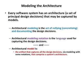
Architecture and UML • In UML, there are five views • Structural view (Class Diagrams, Object Diagrams) • Implementation View (Component Diagrams) • Environment View (Deployment Diagrams) • Behavioral View (Sequence Diagrams, Collaboration Diagrams, Statechart Diagrams, Activity Diagrams)
Component Diagrams • Show relationships and dependencies among sets of code without respect to actual physical placement of code • Use only when there is a design issue
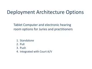
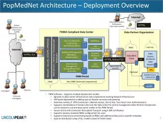
Deployment Diagrams • Called “environment” diagram • Shows actual physical organization of computation units and connectors • Appropriate to do at this stage--when user requirements are fairly well articulated • May surface practical problems • Should use for “what if’s” (volume, network failures, etc.)
The Web • To date, we’ve looked at application objects • Now, we need to look at objects and components in terms of building web applications
Object oriented? • Fundamental component is the page • Web servers distribute pages of information to browsers • Browser acts as generalized user interface container (specifics defined by each page’s content) • Pages may be a combination of static HTML and dynamic scripted pages (ASP)
Scripted Pages • Scripted pages contain code executed by web server (scripting engine or page filter) ultimately building an HTML formatted page • Page is sent back to browser that requests it
Web Client Server • Connection exists only during a page request (connection is broken once the request is fulfilled) • Business logic on the server is only activated by the execution of scripts inside the pages requested by the browser • Ultimate result is to update the business state of the server and prepare an HTML formatted page to the requesting browser
Issues • Business objects are not always accessible when handling individual requests
Client Scripting • As opposed to server side (procedural), are event driven • Have no access to server resources
Forms • Necessary to collect information • Each form associated with an action page • Web server finds page and executes the page’s code
Components • Server -- there may be an intermediate tier with business logic • Client may have components for execution on clients machine. • In order model these effectively, UML extensions have to be used
Stereotypes • Special types of classes and relationships for special, well defined purposes • Use only when necessary • _Really_ necessary for effective web modeling • See www.rational.com/products/whitepapers/100462jsp