Download
1 / 13
140 likes | 253 Views
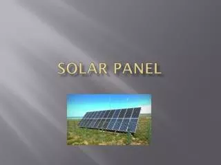
TUSP: The Ultimate Solar Panel. Giancarlo Mesa Jong In Kim Ian Mihalo. The Ultimate Solar Panel (TUSP). TUSP is a light source following solar panel Alternate energy source Increases efficiency against panels that lay flat.

E N D
TUSP: The Ultimate Solar Panel Giancarlo Mesa Jong In Kim Ian Mihalo
The Ultimate Solar Panel (TUSP) • TUSP is a light source following solar panel • Alternate energy source • Increases efficiency against panels that lay flat. • Outdoor test: As much as 1 volt increase when tilting the panel towards the sun as opposed to laying it flat. • Fresnel lenses will be placed over the top of each panel, increasing the amount of light the panels receive. • As the light source moves, the focal point created by the lens will gradually fall off of the board. • Sharp drop in output voltage from solar panels. • The drop in voltage will tell TUSP how to make corrective changes • These changes allow the panels to receive optimum conditions of light by tilting and/or rotating the panels to face the light source.
Experimental Data(Average) • On Average, the Fresnel lenses increased the output voltage by three tenths of a volt. • Still have to decide what threshold voltages will be • As anticipated, when the light source was moved, the focal point gradually fell off of the panel.
Changes in Design • Only using PIC 18F4620 Microchip • 4 analog voltage inputs needed • Voltage regulator Circuits • Microchip 5 volts • Motor 12 volts • Self-sustaining • 2 Rechargeable 9 volt batteries • Addition of Trickle charger circuit • Does not overcharge batteries
Specifications • 4 Solar Panels • 95.25 mm X 63.5 mm • 4Vdc, 100mA
Specifications • 4 Fresnel Lenses • 95mm X 135mm X 0.4mm • Focal Length 120mm • For best results, lenses will be placed at this length.
Specifications • 2 Stepper Motors • 4 Phase 12V, 40mA • 30 ohms Resistance • Angle: 7.5°/85.25 • Torque 350 g.cm
Motor Testing • Rotation • Clockwise • Counter Clockwise • Performance unimplemented • Smooth rotation • Performance implemented (solar panel inputs) • Choppy rotation • Sampling time
Technical Problems • Focal point acquisition • Correct response as source moves • Threshold changes constantly • Maximize efficiency • Testing needs to have constant environment • Finish code to give proper step response to stepper motors
Fresnel Lens Solar Panel Trickle Charger Batteries ~18v LCD PIC 18F4620 Regulator Circuitry Direction Control Stepper Motors
Summary • Changes in design: • Self-sustaining • Using the 18F4620 chip only • Trickle charger circuit • Properly charges the batteries • Voltage regulator circuit • Make sure components are not overloaded.