Download
1 / 17
170 likes | 357 Views
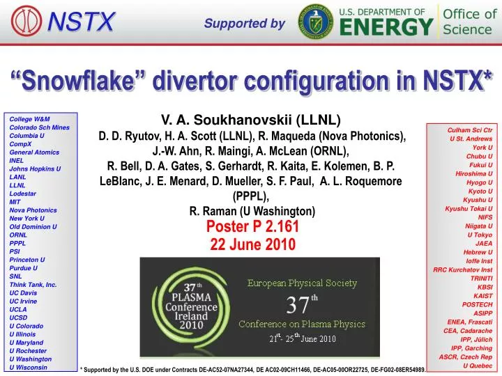
NSTX. Supported by. “Snowflake” divertor configuration in NSTX*. V. A. Soukhanovskii (LLNL) D. D. Ryutov, H. A. Scott (LLNL), R. Maqueda (Nova Photonics), J.-W. Ahn, R. Maingi, A. McLean (ORNL),

E N D
NSTX Supported by “Snowflake” divertor configuration in NSTX* V. A. Soukhanovskii (LLNL) D. D. Ryutov, H. A. Scott (LLNL), R. Maqueda (Nova Photonics), J.-W. Ahn, R. Maingi, A. McLean (ORNL), R. Bell, D. A. Gates, S. Gerhardt, R. Kaita, E. Kolemen, B. P. LeBlanc, J. E. Menard, D. Mueller, S. F. Paul, A. L. Roquemore (PPPL), R. Raman (U Washington) College W&M Colorado Sch Mines Columbia U CompX General Atomics INEL Johns Hopkins U LANL LLNL Lodestar MIT Nova Photonics New York U Old Dominion U ORNL PPPL PSI Princeton U Purdue U SNL Think Tank, Inc. UC Davis UC Irvine UCLA UCSD U Colorado U Illinois U Maryland U Rochester U Washington U Wisconsin Culham Sci Ctr U St. Andrews York U Chubu U Fukui U Hiroshima U Hyogo U Kyoto U Kyushu U Kyushu Tokai U NIFS Niigata U U Tokyo JAEA Hebrew U Ioffe Inst RRC Kurchatov Inst TRINITI KBSI KAIST POSTECH ASIPP ENEA, Frascati CEA, Cadarache IPP, Jülich IPP, Garching ASCR, Czech Rep U Quebec Poster P 2.161 22 June 2010 * Supported by the U.S. DOE under Contracts DE-AC52-07NA27344, DE AC02-09CH11466, DE-AC05-00OR22725, DE-FG02-08ER54989.
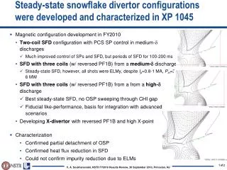
Abstract The studies of an innovative "snowflake" divertor (SFD) configuration in the National Spherical Torus Experiment (NSTX) provide support to this plasma-material interface concept as a promising candidate for future tokamaks and spherical tokamak based devices with high heat flux divertors. A number of theoretically predicted geometric and radiative properties of the SFD configuration [1-4] have been confirmed in experiments at NSTX. The obtained SFD showed evidence of impurity control and divertor heat flux reduction. The SFD configuration was obtained in 1 MA 4-6 MW NBI-heated H-mode discharges with PSOL ~ 3 MW. Two divertor coils with 4 and 12 kA current waveforms controlled by the plasma control system were used to generate the SFD. A very high poloidal flux (area) expansion of the separatrix region in the SFD, a longer connection length and a larger divertor scrape-off layer (SOL) volume (as compared to standard NSTX divertor configurations) led to a partial detachment of the first several mm of the SOL width (as mapped to the midplane). Divertor heat flux profiles showed a significant reduction of the peak values, accompanied by an increase in divertor radiated power. A volume recombination zone with Te ~ 1.5 eV, ne ~ 2-6 x 10²⁰ m-3 developed in the X-point and strike point regions, suggesting an increase in volumetric momentum losses in the divertor. The core carbon density was reduced by up to 50 % in the SFD discharges with no degradation of H-mode stored energy and confinement. [1] D. D. Ryutov, Phys. Plasmas 14, 64502 (2007) [2] D. D. Ryutov et. al., Phys. Plasmas 15, 092501 (2008) [3] D. D. Ryutov et al., Paper IC/P4-8, 22st IAEA FEC, Geneva, Switzerland, 10/2008 [4] M. V. Umansky et al., Nucl. Fusion 49, 075005 (2009)
Overview and Summary • “Snowflake” divertor configuration – a promising solution for divertor heat flux mitigation in future fusion plasma devices • “Snowflake” divertor configuration (cf. standard divertor) • Higher flux expansion (increased divertor Awet) • Higher divertor volume (increased Prad, Rrec, Rcx) • Existing divertor magnetic coils for control • In recent NSTX experiments • “snowflake” divertor was generated with 2 divertor coils • H-mode confinement maintained • “snowflake” divertor led to outer strike point partial detachment • significant reduction in peak heat flux • reduction of core impurities • predicted “snowflake” divertor geometry properties confirmed
Various techniques considered for SOL / divertor q|| and qpk control • Divertor heat flux mitigation solutions: • Divertor geometry (poloidal flux expansion) • Strike point sweeping • Radiative divertor (or radiative mantle) • Divertor plate tilt and divertor magnetic balance • Candidate solutions • be compatible with good core plasma performance (H-mode confinement, MHD, ELM regime, density) and particle control • scale to very high qpeak (15 - 80 MW/m2) for future devices
Open divertor geometry and extensive divertor diagnostics enable divertor configuration studies in NSTX • Plasma facing components • ATJ and CFC graphite tiles • Lithium coatings from overhead lithium evaporators
Theory predicts attractive divertor geometry properties in “snowflake” divertor configuration Ideal “snowflake” divertor “snowflake”-plus “snowflake”-minus divertor configurations • Proposed by D. D. Ryutov (LLNL) • Phys. Plasmas 14, 064502 (2007) • 34th EPS Conference on Plasma Phys. Warsaw, 2 - 6 July 2007 ECA Vol.31F, D-1.002 (2007) • Phys. Plasmas, 15, 092501 (2008) • Paper IC/P4-8 at IAEA FEC 2008 • SFD is obtained by creating a second-order poloidal null in the (lower) divertor with existing divertor coils • Predicted properties (cf. standard divertor) • Lower Bp in X-point region • Larger Awet , fexp • Larger X-point connection length Lx • Larger effective divertor volume Vdiv • X-point flux tube squeezing – barrier for turbulence? • ELM control (increased edge magn. shear) ?
ISOLVER code was used to obtain strike point positions and divertor coil currents of “snowflake” configuration Modeled “snowflake” divertor configurations • ISOLVER - predictive free-boundary axisymmetric equilibrium solver was used to model divertor coil currents for NSTX “snowflake” configurations Standard divertor configuration “Snowflake” divertor configurations obtained in NSTX + + Null-point separation d
In experiment, “snowflake” divertor configuration was obtained via controlled outer strike point scan • Scanned OSP between 0.44 to 0.73 m on a shot-to-shot basis • Best “snowflake” configurations were obtained with requested ROSP ~ 0.55 m (not necessarily actual ROSP) • “Snowflake” configuration was obtained when null-point separation d decreased to below 20 cm
Theoretically predicted geometrical properties of the snowflake divertor configuration are confirmed in NSTX • In “snowflake” divertor • Plasma-wetted area (flux expansion) higher by up to 50 % • Lx longer (thus fPFR and Vdiv higher) • These properties observed in first 2-3 mm of SOL lq
H-mode confinement retained with “snowflake” divertor, core Prad and nC reduced by up to 75 % • Used 80-100 g evaporated lithium per discharge for wall conditioning • ELM-free H-mode discharges had impurity accumulation • In “snowflake” divertor discharges • Divertor sputtering source reduction (?) • Edge confinement degradation (?)
Partial detachment of outer strike point region observed in “snowflake” divertor discharges • Signs of partial detachment observed in “snowflake” divertor • Loss of parallel pressure • Heat and particle flux reduction at the plate • Te ≤ 1.6 eV, ne ≥ 2e14 m-3 • Increase in divertor Prad • Increase in 3-body recombination rate • Increase in neutral pressure
Significant reduction of heat flux observed in “snowflake” divertor • Divertor peak heat flux well correlated with null-point separation d • Reduction observed in 2-3 mm region (mapped to midplane) adjacent to separatrix • Shown heat fluxes are in uncalibratedrelative units (IR camera data not calibrated due to lithium coatings)
Divertor particle flux decreased, Balmer-a intensity increased (due to recombination) in “snowflake” divertor • Divertor Da emission • Increase in radiating zone width • Brightness increase (due to recombination) correlated with Langmuir probe Isat decrease (due to particle flux reduction)
High-n Balmer line emission measurements suggest high divertor recombination rate, low Te, high ne • Balmer series spectra modeled with CRETIN; Spectra sensitive to • Line intensity <-> Recombination rate • Te <-> Boltzman population distribution • ne <-> Line broadening due to linear Stark effect from ion and electron microfield “snowflake” standard • Te=0.8-1.2 eV, ne=2-7 x 10²⁰ m-3inferredfrom modeling
Divertor camera images show formation of extended radiation zone in “snowflake” divertor Center stack gas puff • Visible camera images (~ 400 – 750 nm bandpass) • Larger radiative zone in “snowflake” divertor (cf. standard divertor)
Volumetric power and momentum losses are increased due to geometry in “snowflake” divertor • Hulse-Post non-coronal radiative cooling curves for low Z impurities for n0/ne, ne-recy • Calculate max q|| that can be radiated • Express max q|| as function of distance from heat source for range of fz(Post JNM 220-222, 1014 (1995) ) • Power losses due to deuterium Prad and ionization not considered • For NSTX, use n0 = 0.1 % and ne-recy = nex 1e-3s • Electron-ion recombination rate depends on divertor ion residence time • Ion recombination time: ion~ 1−10 ms at Te =1.3 eV • Ion residence time:ion 3-6 ms
Future plans • Magnetic control of “snowflake” divertor • RT-control of 2nd null-point with PCS • Use of PF1B for control • Transport and turbulence characterization • Edge stability characterization • Scaling with power • High-performance plasma scenario with lithium conditioning and reduced core impurities • NSTX-Upgrade (Poster P2.106 by J. E. Menard) • Additional divertor coil PF1C • flux expansion variation with fixed X-point height and strike-point location • Development of PMI solutions to address • 2-3x higher input power • up to 30 % reduction in Greenwald fraction • 3-5 xlonger pulse duration