Download
1 / 15
150 likes | 323 Views
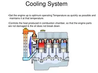
SiPM Fiber Tracker Cooling System Solutions. Michele Battistin – Enrico D a Riva CERN Engineering Department Cooling and Ventilation Group Workshop on SiPM cooling for Fiber Tracker CERN, 17 th October 2013. AGENDA. Perfluorocarbon or not perfluorocarbon?? evaporative solution

E N D
SiPM Fiber Tracker Cooling System Solutions • Michele Battistin – Enrico Da Riva • CERN Engineering Department • Cooling and Ventilation Group • Workshop on SiPM cooling for FiberTracker • CERN, 17th October 2013 M. Battistin - E. Da Riva
AGENDA • Perfluorocarbon or not perfluorocarbon?? • evaporative solution • mono-phase solution • Details on the pre-study for SiPM cooling M. Battistin - E. Da Riva
TOTEM Roman Pots C3F8 Evaporative Cooling System Eng Spec EDMS 778214 v1 POTS STATIONS LOCATION XRP1 XRP1 XRP3 XRP3 Main station DESIGN PARAMETERS M. Battistin - E. Da Riva
Roman Pot cooling Evaporative system @ C3F8 2006 costs M. Battistin - E. Da Riva
TOTEM RP cooling C3F8 main working points M. Battistin - E. Da Riva
TOTEM RP Cooling System Schematic M. Battistin - E. Da Riva
Could C3F8 or C2F6 Evaporative System Be the Solution for SiPM Fiber Tracker? • The solution has already been used for TOTEM Roman Pots and ATLAS Blends • Low operation temperature easily achivable (-43°C during Totem tests with C3F8 – lower with C2F6); • Low opeartion pressure on the detector (0.8 - 1 bara); • Temperature stability and uniformity is granted by the evaporation pressure; • Tranfer lines operates at ambient temperature: can be very long (300 m for Totem). The cooling station can be in an accessible area (no operation in the protected zone); • Known technology both on detector structure than on the cooling system • The system is running since 2007 with high reliability; • Cost estimate (based on TOTEM and ATLAS-Blends cooling): • Cooling station 250 kCHF @ 2007 (EN-CV-DC mechanical and electr. construction); • Copper not insulated transfer lines 30-50 kCHF; • Manifolding ?? • Do we need to use C3F8? NO • No radiation -> other industrial refrigerants (more green) could be studied (R23; R125;…) M. Battistin - E. Da Riva
A mono-phase system ?? Chiller 1 -50°C 8 kW liquid tank 2 redundant pumps 3 m3/h Manual on/off valve Cryo extension SiPM Fiber Tracker Chiller 2 -50°C 8 kW Manual regul valve Cryo extension Manual on/off valve Cryo extension T regulation heater UX85 protected UX85 experiment Filter section Transfer Line(s) For each distribution line - Large cost reduction possible reducing loops number M. Battistin - E. Da Riva
Could C6F14 Mono-phase System Be the Solution for SiPM Fiber Tracker? • The solution has already been used for 13 cooling systems for LHC Exp. detectors • LHCb Inner Tracker, Trigget Traker, Rich1&2; • Low operation temperature easily achivable (-50°C or less) depending on chiller selection; • Low opeartion pressure on the detector (3-5 bar); • Temperature stability and uniformity is granted by a fast T regulation heater; • Tranfer lines shall be insulated (0.5 K temperature rise – see: E. Da Riva); • Known technology both on detector structure than on the cooling system • Refers to E. da Riva presentation this morning for the on-detector solution; • Cost estimate (based on LHCb IT-TT-Rich cooling systems) • Cooling station: 140-180 kCHF @ 2013 (tendered); • Insulated transfer lines 80-100 kCHF; • Manifolding: about 1500 CHF/cooling loop (based on 48 loops of 6 modules – see E. Da Riva presentation); • Do we need to use C6F14? NO • No radiation -> other industrial (more green) fluids are available (NOVEC646 – see: E. Da Riva). M. Battistin - E. Da Riva
Conclusions • Perfluorocarbons have no advantages: alternative fluids can be used in the same process installation. • Liquid mono-phase cooling appears more appealing for • cooling system simplicity (installation & maintenance cost) • cooling efficiency (operation cost) • Two-phases allows warm small pipe distribution up to the protected “enclave” (integration issues) M. Battistin - E. Da Riva
Thanks for your attention You can find as back-up the details of the C6F14single-phase cooling system preliminary designdone by Enrico Da Riva “Order of magnitude estimate for open discussion” M. Battistin - E. Da Riva
Chiller ~70 m manual ON-OFF valve 6 modules connected in series liquid tank • Very simple design, as compared to traditional two-phase systems, which would require 288 capillaries, automatic pressure regulation valve(s), (two-stage) compressor, lubricant-free compressor or dealing with oil return issues, higher system pressure …; • Only evident drawback: lines must be insulated, while two-phase system can have warm lines up to the capillaries and heater or water heat exchanger at the modules outlet; • Temperature stability demanded to the chiller only, no other regulation needed (constant heat load); • C6F14 is not binding, “green” fluids such (e.g. its substitute NOVEC649) can be used, but tests needed. manual FLOW REGULATION valve X 48 branches manual ON-OFF valve M. Battistin - E. Da Riva
MAIN COMPONENTS • Chiller power: 5~8 kW @ -50°C (~5 kW from modules in the very worst case scenario assuming 20 W per module, ~3 kW due to heat pick-up along lines); • Pump: 3.3 m3/h, Δp ≤ 3 bar; • Mass of C6F14: ~300 kg; • 96 on/off valves (2 per branch); • 48 manual flow regulation valves (1 per branch); • Liquid tank / expansion vessel (~200 L); • 336 connectors between modules; MAIN DISTRIBUTION LINE • DN32 (o.d. 42 mm), 1 m/s, 70 m + 70 m (a/r); • 5 cm armaflex insulation, Tsurface ~ 17°C, heat pick-up ~12 W/m; • Temperature rise along 70 m: ~ 0.5 K; • Δp along 70 m + 70 m ≤ 1 bar M. Battistin - E. Da Riva
MODULES LINES • 48 branches, 6 modules fed in series; • i.d. 4 mm, o.d. 6 mm, 1.5 m/s; • 3 cm armaflex insulation, Tsurface ~ 17°C, heat pick-up ~ 6 W/m; • Refrigerant temperature rise along 5 m of insulated line: <1 K; • Refrigerant temperature rise through 6 modules: 3.6 K [assuming 20 W per module]; • HTC: 1200 Wm-2K-1, refrigerant-to-wall ΔT: 2.6K [assuming 20 W per module]; • Δp through 6 modules (3 m + 24 bends) ≤ 1 bar. EXPECTED SILICON DIE TEMPERATURE (worst case scenario) • Assumption, ΔT through ceramic stiffener, flex-cable, teflonsubstrate < 3K; • Silicon die at the beginning of the first module fed: -43.9°C; • Silicon die at the end of the last module fed: -40.3°C. M. Battistin - E. Da Riva
Serial vs parallel module connection Serial connection is to be preferred to parallel connection: • Much lower length to insulate → easier to install, lower heat load; • Optimal flow rate in every module (good for HTC inside the pipes and heat pick up); • Connectors can be installed between each module: in case of problems the two on/off valves can be closed, only 6 modules over 288 will be off, the faulty module alone can be removed. ~3m M. Battistin - E. Da Riva