Download
1 / 64
680 likes | 993 Views
Chapter 7 Memory and Programmable Logic. 7-1 Introduction. 7-2 Random-Access Memory. 7-3 Memory Decoding. 7-4 Error Detecting and Correction. Chapter 7 Memory and Programmable Logic. 7-5 Read-only Memory. 7-6 Programmable Logic Array. 7-7 Programmable Array Logic.

E N D
Chapter 7 Memory and Programmable Logic 7-1 Introduction 7-2 Random-Access Memory 7-3 Memory Decoding 7-4 Error Detecting and Correction
Chapter 7 Memory and Programmable Logic 7-5 Read-only Memory 7-6 Programmable Logic Array 7-7 Programmable Array Logic 7-8 Sequential Programmable Devices
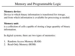
7-1 Introduction Random-Access Memory (RAM) Memory Read-only Memory (ROM) Can perform both the write and read operation A device to which binary information is transferred for storage and from which information is available when needed for processing. Programmable Logic Array (PLA) Programmable Logic Device (PLD) Can only read, cannot write Programmable Array Logic (PAL) Field-Programmable Gate Array (FPGA)
7-1 Introduction Array Logic Diagram Programmable Fixed
7-2 Random-Access Memory Bit : the smallest unit of binary data Byte : an 8-bit unit Nibble : a 4-bit unit Word : a complete unit of information and generally consists of one or more bytes Cell : the storage element in a memory that can retain either a 1 or a 0
7-2 Random-Access Memory Block Diagram of a Memory Unit The n data input lines provide the information to be stored in memory and n data output lines supply the information coming out of memory.
7-2 Random-Access Memory The k address lines that specify the particular word chosen among the many available.
7-2 Random-Access Memory The two control input specify the direction of transfer desired: the read input and the write input.
7-2 Random-Access Memory For example, the memory unit with a capacity of 1K words of 16 bits each. 1K=1024=210and 16 bits constitute twobytes. The address varies from 0 to 1023.
7-2 Random-Access Memory Write and Read Operations The steps that must be taken for the purpose of transferring a new word to be stored into memory are as follows: 1. Apply the binary address of the desired word to the address lines. 2. Apply the bits that must be stored in memory to the data input lines. 3. Activate the write input.
7-2 Random-Access Memory The steps that must be taken for the purpose of transferring a stored word out of memory are as follows: 1. Apply the binary address of the desired word to the address lines. 2. Activate the read input.
7-2 Random-Access Memory The memory enable is used to enable the particular memory chip in a multiple implementation of a large memory. The Read/Write input determines the operation to be performed. Most integrated-circuit memory components provide two other control inputs:
Two control inputs: Enable and ReadWrite DataIn lines have four bits. Example that illustrated the operation of a memory 7-2 Random-Access Memory Memory Description in HDL //Read and write operations of memory. //Memory size is 64 words of 4 bits each. module memory (Enable,ReadWrite,Address,DataIn,DataOut); input Enable,ReadWrite; input [3:0] DataIn; input [5:0] Address; output [3:0] DataOut; reg [3:0] DataOut; reg [3:0] Mem [0:63]; //64 x 4 memory always @ (Enable or ReadWrite) if (Enable) if (ReadWrite) DataOut = Mem[Address]; //Read else Mem[Address] = DataIn; //Write else DataOut = 4'bz; //High impedance state endmodule
The input address has 6 bits. 26=64 Memory is declared with a reg keyword 7-2 Random-Access Memory Memory Description in HDL //Read and write operations of memory. //Memory size is 64 words of 4 bits each. module memory (Enable,ReadWrite,Address,DataIn,DataOut); input Enable,ReadWrite; input [3:0] DataIn; input [5:0] Address; output [3:0] DataOut; reg [3:0] DataOut; reg [3:0] Mem [0:63]; //64 x 4 memory always @ (Enable or ReadWrite) if (Enable) if (ReadWrite) DataOut = Mem[Address]; //Read else Mem[Address] = DataIn; //Write else DataOut = 4'bz; //High impedance state endmodule
Declared with a reg keyword 7-2 Random-Access Memory Memory Description in HDL //Read and write operations of memory. //Memory size is 64 words of 4 bits each. module memory (Enable,ReadWrite,Address,DataIn,DataOut); input Enable,ReadWrite; input [3:0] DataIn; input [5:0] Address; output [3:0] DataOut; reg [3:0] DataOut; reg [3:0] Mem [0:63]; //64 x 4 memory always @ (Enable or ReadWrite) if (Enable) if (ReadWrite) DataOut = Mem[Address]; //Read else Mem[Address] = DataIn; //Write else DataOut = 4'bz; //High impedance state endmodule DataIn lines have four bits.
Read Operation Write Operation The memory has three-state output 7-2 Random-Access Memory Memory Description in HDL //Read and write operations of memory. //Memory size is 64 words of 4 bits each. module memory (Enable,ReadWrite,Address,DataIn,DataOut); input Enable,ReadWrite; input [3:0] DataIn; input [5:0] Address; output [3:0] DataOut; reg [3:0] DataOut; reg [3:0] Mem [0:63]; //64 x 4 memory always @ (Enable or ReadWrite) if (Enable) if (ReadWrite) DataOut = Mem[Address]; //Read else Mem[Address] = DataIn; //Write else DataOut = 4'bz; //High impedance state endmodule
7-2 Random-Access Memory Timing Waveforms Write cycle timing waveform The address and input data are applied to the memory at the beginning of the T1
7-2 Random-Access Memory Timing Waveforms The memory enable and the Read/Write signals must be activated after the signals in the address lines are stable.
7-2 Random-Access Memory Timing Waveforms The memory enable and the Read/Write signals must stay active for at least 50 ns ( cycle time ) The time required to complete a write operation.
7-2 Random-Access Memory Timing Waveforms The address and data signals must remain stable for a short time after the control signals are deactivated.
7-2 Random-Access Memory Timing Waveforms Read cycle timing waveform The memory enable and Read/Write signals must be high level for a read operation
7-2 Random-Access Memory Timing Waveforms The memory enable and Read/Write signals must be high level for a read operation
7-2 Random-Access Memory Types of Memories such as RAM Random-Access Memory (RAM) Memory Magnetic disk, ROM Sequential-Access Memory Low power consumption and large storage capacity, but need to refresh Volatile Faster to access and no need to refresh Memory nonvolatile Static RAM (SRAM) RAM Dynamic RAM (DRAM)
7-3 Memory Decoding Internal Construction Logic Diagram of Memory Cell Block Diagram of Memory Cell
7-3 Memory Decoding The decoder is enabled with the memory enable input. Once a word has been selected, the Read/Write determines the operation.
0 0 1 1 0 0 1 1 7-3 Memory Decoding Read Operation: 0 1 1 1
0 0 1 1 0 0 1 1 7-3 Memory Decoding Write Operation: 0 1 1 0
10×1024 decoder . 1024 7-3 Memory Decoding Coincident Decoding Need 64 AND gates Need 1024 AND gates
7-3 Memory Decoding 1 Address Multiplexing 0 To reduce the number of the pins in the IC package. 8-bit row address
7-3 Memory Decoding 0 Address Multiplexing 1 8-bit column address
7-3 Memory Decoding 1 Address Multiplexing 0 To reduce the number of the pins in the IC package. 8-bit row address
P1 = XOR of bits ( 3, 5, 7, 9, 11) = 0 P2 = XOR of bits ( 3, 6, 7, 10, 11) = 0 P4 = XOR of bits (5, 6, 7, 12) = 1 P8 = XOR of bits (9, 10, 11, 12) = 1 7-4 Error Detection and Correction Hamming Code For example, the 8-bit data word 11000100, including 4 parity bits, one of the most common error-correcting codes that devised by R.W. Hamming Bits position: 1 2 3 4 5 6 7 8 9 10 11 12 P1P2 1 P4 1 0 0 P8 0 1 0 0 those position numbered a as a power of 2 are reserved for the parity bits.
C1 = XOR of bits ( 1,3, 5, 7, 9, 11) C2 = XOR of bits ( 2,3, 6, 7, 10, 11) C4 = XOR of bits (4,5, 6, 7, 12) C8 = XOR of bits (8,9, 10, 11, 12) 7-4 Error Detection and Correction Then, 12-Bit word stored in memory: Bits position: 1 2 3 4 5 6 7 8 9 10 11 12 0 0 1 1 1 0 0 1 0 1 0 0 4 check bit :
C1 C2 C4 C8 For no error : 0 0 0 0 With error in bit 1 : 0 0 0 1 With error in bit 5 : 0 1 0 1 7-4 Error Detection and Correction • Determine error
7-4 Error Detection and Correction • Determine Range of Data Bits Range of Data Bits of k Check Bits In general, the Hamming code consists of k check bits and n data bits. Giving the relationship 2k > n + k
7-4 Error Detection and Correction • Grouping of bits for parity and checking The least significant bit is a 1 in the binary number 1,3,5,7,9,11 P1 = XOR of bits ( 3, 5, 7, 9, 11)
7-4 Error Detection and Correction • Grouping of bits for parity and checking The least significant bit is a 1 in the binary number 2,3,6,7,11 P2 = XOR of bits ( 3, 6, 7, 10, 11)
7-4 Error Detection and Correction • Grouping of bits for parity and checking The least significant bit is a 1 in the binary number 2,3,6,7,11 P2 = XOR of bits ( 3, 6, 7, 10, 11) P3 and P4 are determined in the similar way.
7-4 Error Detection and Correction Single-Error Correction, Double-Error Detection The Hamming code can detect and correct only a single error. By adding anothing parity bit to the coded word, the Hamming code can detect double errors. For example, the previous 12-bitcoded word 001110010100P13 P13 = XOR ( other 12 bits) P = XOR ( all 13 bits)
7-4 Error Detection and Correction Single-Error Correction, Double-Error Detection
7-5 Read-Only Memory A read-only memory ( ROM ) is essentially a memory device in which permanent binary information is stored. ROM Block Diagram The binary information stays within the unit even when power is turned off.
There are 5 input lines that form the binary numbers from 0 to 31 for the address. 7-5 Read-Only Memory ROM Block Diagram Consider a 32X8 ROM
The 5-to-32-line address decoder 32X8 storage array 7-5 Read-Only Memory Consider a 32X8 ROM
Data output lines 7-5 Read-Only Memory Consider a 32X8 ROM
7-5 Read-Only Memory Programming the ROM The hardware procedure that programs the ROM results in blowing fuse links according to a given truth table.
The 0 in the word are programmed by blowing the fuse links between output of decoder and the inputs of OR gates. 7-5 Read-Only Memory Programming the ROM
The 1 in the word are marked in the diagram with a X to denote a connection in place of a dot used for permanent connection in logic diagram. 7-5 Read-Only Memory Programming the ROM
7-5 Read-Only Memory Combinational Circuit Implementation The ROM may be considered as a combinational circuit with eight outputs, each being a function of the five input variables.
7-5 Read-Only Memory Combinational Circuit Implementation Output A7 can be expressed in sum of minterms as A7= ( 0,2,3,…,29 )
7-5 Read-Only Memory Types of ROM It can be restructured to the initial state even through it has been programmed previously. Mask Programming It can be erased with an electrical signal instead of ultraviolet light. PROM ( Programmable ROM ) ROM EPROM It is done by the semiconductor company and is economical only if a large quantity of the same ROM configuration is to be ordered. EEPROM or E2PROM