Download
1 / 12

E N D
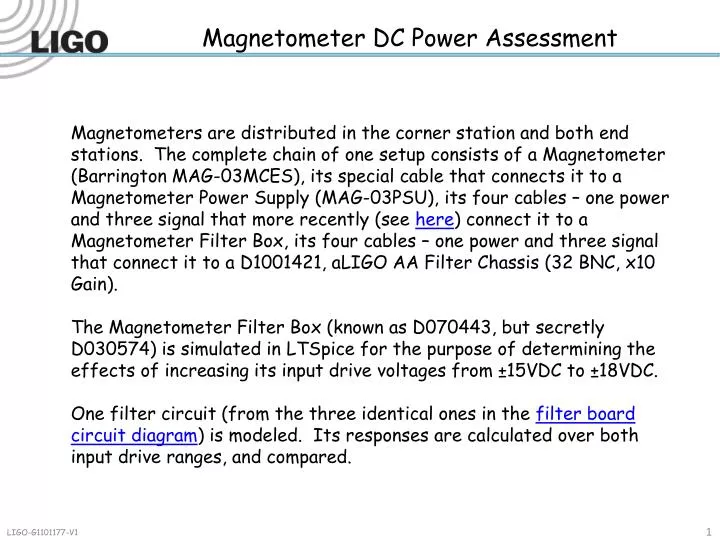
Magnetometer DC Power Assessment Magnetometers are distributed in the corner station and both end stations. The complete chain of one setup consists of a Magnetometer (Barrington MAG-03MCES), its special cable that connects it to a Magnetometer Power Supply (MAG-03PSU), its four cables – one power and three signal that more recently (see here) connect it to a Magnetometer Filter Box, its four cables – one power and three signal that connect it to a D1001421, aLIGO AA Filter Chassis (32 BNC, x10 Gain). The Magnetometer Filter Box (known as D070443, but secretly D030574) is simulated in LTSpice for the purpose of determining the effects of increasing its input drive voltages from ±15VDC to ±18VDC. One filter circuit (from the three identical ones in the filter board circuit diagram) is modeled. Its responses are calculated over both input drive ranges, and compared.
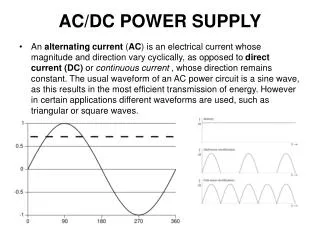
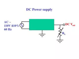
Magnetometer Filter Box Recent Addition The required voltage range is 9 to 18 VDC. The power supply can be the standard 18V power sources. (Note that this AC version is only applicable in the corner station. The end stations had this connected to a 12VDC DIN rail supply.) The required voltage source is really ±15VDC. This discussion is intended to determine if the standard 18V power sources can be used for this device.
MAG-03MCES - MAG-03PSU - D070443 Magnetometer: Bartington Instruments MAG-03MC On/Off Magnetometer Power Supply (MAG-03PSU) D070443 Magnetometer Filter Magnetometer MAG-03MCES X Y Z X Y Z X Y Z 5 meter Pin 1: +15VDC … Red/Blk RED Pin 2: Ground … Red/Blk BLACK Pin 3: -15VDC … Wht/Blk WHITE Pin 4: Ground … Wht/Blk BLACK Black – G/W … Ground Stria – Y/W … +12VDC Powered from 12VDC DIN rails – + Powered from 15VDC DIN rails Charger … 9 to 18 VDC
Magnetometer Filter Box Simulation One filter circuit was modeled in LTSpice. It was assigned input control voltages of ±15VDCand its transfer function and transient response were calculated. When the circuit gain was observed, two stimulus voltages were chosen (.1V and .175V) that would demonstrate the difference in clipping results. A second identical circuit was likewise modeled. It was assigned input control voltages of ±18VDC and its transfer function and transient response were also calculated. The responses were compared and are presented.
Circuit 1: ±18VDC – Transfer Function Circuit 1: Transfer Function
Circuit 2: ±15VDC – Transfer Function Circuit 2: Transfer Function
Circuit 1: ±18VDC - Clipping Circuit 1: Transient Analysis @ .1V Circuit 1: Transient Analysis @ .175V
Circuit 1: ±15VDC - Clipping Circuit 2: Transient Analysis @ .1V Circuit 2: Transient Analysis @ .175V
Circuits 1 & 2 – Clipping Comparison Clipping occurs as a function of input control voltage.
Conclusions There is no difference in transfer function versus input voltages. The difference in the clipping value follows the input voltages, that is, the effective full range of the output signal is increased relative to a larger full range of the input voltages. This is only a problem is these filters are intended to clip their signals at 15V. The gain of the circuit is around 100, which makes the gain of each channel around 1000, due to the x10 gain in the AA channel. The standard 18V power strips can be used to source the voltage for both the MAG-03PSU and the D070443 Filter Box.
Other Observations On one of the MAG-03PSU power supplies (serial number 0539) there is an additional connector just below the DC power socket. It is a 3-pin LEMO and the pin-out diagram that is taped to the device is NOT correct. There is no internal connection of the -18v pin. No internal connection exists for the pin labeled -18v.