Download
1 / 27
270 likes | 404 Views
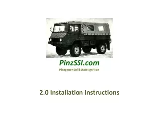
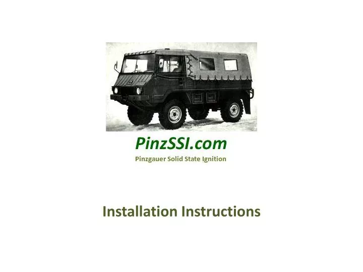
Installation Instructions. Original distributor, coil, and plug wires. Your PinzSSI kit will contain these items. Packing List. Coil/Relay assembly Mounting bracket Spark Plugs (4) Spark Plug Wires (4) Cable ties (10) Module Wire loom (5’) Red wire for battery tap Installation CD

E N D
Packing List Coil/Relay assembly Mounting bracket Spark Plugs (4) Spark Plug Wires (4) Cable ties (10) Module Wire loom (5’) Red wire for battery tap Installation CD ‘On-Off’ toggle switch Parts package Butt sleeves (6) Spade connectors (6) Boot grease Vacuum plug Heat shrink Plug Wire spacers PinzSSI sticker Be sure to use the correct tool for crimping the butt sleeves and spade connectors. Otherwise, the connection may eventually fail. Don’t use pliers. This is very important! Use heat shrink on all connections.
The heart of the system is the wiring harness and power module. The harness also has seven colored wires and the coil pack harness plug.
Cut ignition feed here Begin by removing the coil and bracket, suppressor, and distributor. Cut off the ignition power source wire at the suppressor connection.
Plug vacuum port Remove spark plugs and wires. Remove vacuum line and block the port with the provided plug. Remove the pinch clamp from the distributor and save for use on the new ignition module.
Remove the bolt near the top of the driver’s side spring. This holds the heater hose clamp in place as shown.
Using the longer provided bolt, install the mounting bracket.
This side towards the engine Bolt hole Bolt the coil/relay pack onto the mounting bracket using the provided bolt.
Wire ties Ground connection Wire ties Remove the cover plate between the air tunnel and the engine. Route the harness as shown. Connect the black ground wire from the module to the screw holding the Molex connector.
You could also route the harness over the top of the engine in the vicinity of where the spark plug wires used to run, and secure with wire ties. This is a matter of preference.
Module harness Covered yellow wire Ignition wire to relay 24v ignition wire splice Install pinch clamp onto the module and install the module into the engine block, making sure that the stem goes in all the way. The wiring harness exiting the module should go towards the front of the vehicle. Connect the yellow wire from the harness to the white 24v ignition wire that was cut off earlier. Install heat shrink. Route the harness behind the voltage regulator, keeping the harness away from the fan belt. Work the slack towards the coil/relay. Secure the wiring into place using wire ties.
Battery box hole 12 volt feed Route the power feed from the battery box by either 1) using the existing hole as shown or 2) drilling a hole. The photo shows using the existing hole (from under the vehicle), the same hole that the other battery cables use. The fit is tight! Leave enough slack to reach the battery terminal as shown, but do not connect at this time. The PinzSSI system works on 12 volts. Be sure to verify voltage as there are several possible battery configurations. The photo shown is just one possibility, which reflects the original factory set-up. Do not use the ignition switch wire to power the module. This will damage the module and void the warranty! The 24 volts from the ignition powers the relay solenoid only. Use provided wire loom to cover the wire after installation.
2) 12 volt feed from the battery 1) 24 volt ignition feed (yellow) 3) 12 volt feed to the new harness (red) This also feeds tach voltage if applicable. At the relay make the following 3 connections- 1) 24 volt feed from the ignition switch, 2) 12 volt feed from the battery, and 3) 12 volt feed to the new harness. Leave the harness unplugged from the coil pack until after the timing is set!
Reconnect the battery with the new power feed. Be sure it is 12 volts! Provisions to make the battery connection are NOT included with the kit.
Here is a simple schematic of the interconnections between the battery, relay, ignition key, and the new wiring harness. The module draws just 660 mA, not enough to interfere with the charging system or shorten the life of either battery. Note- 24v to 12v DC converters have been tested to replace the battery 12v connection. All converters failed except for the more expensive versions, as they do not produce a smooth enough voltage for the module to operate.
The PinzSSI ignition system has 2 possible advance curves programmed into the module. A toggle switch allows the driver to choose between a normal curve to a less aggressive curve. ‘On’ is the normal curve (on road). ‘Off’ is the less aggressive curve for heavy loads. The pre-assembled switch is mounted in the cab by using the 2 screws which hold the windshield washer bottle in place.
The switch comes with a harness connected which consists of a brown wire. Mount the switch and run the wiring along the hydraulic lines, covering with loom and securing with wire ties. Run the wire through the hole with the hydraulic lines and connect with the same color on the harness (brown) and heat shrink. Ground the blue wire to the chassis. The green wire feeds the tachometer at the rate of 2 pulses per crankshaft revolution, if you have a tach to be connected. A wire to the tach could be run in the same loom. Some adjustment of the tach dip switches may be necessary, including the potentiometer. If you don’t want to bother with mounting the switch, connect the blue and brown wires together where they exit the harness and ground to the vehicle chassis. This defaults to the ‘On’ curve, which is the normal advance curve.
The module is a computer which takes readings from the optical sensor and sends the info to the CPU. This includes RPM and rate of engine acceleration/deceleration. The CPU adjusts the ignition timing based on the 2 programmed advance curves- ‘On’ and ‘Off’. The timing is 0 degrees while the engine cranks, and jumps to 22 degrees BTDC at about 300 RPM. From there the maximum total advance reaches 38 degrees at 3500 RPM. It is important to set the static timing (timing set with engine not running) at 0 degrees, or TDC, because this is the reference point that the computer uses for the rest of the curve. The spark plugs fire 3 times every time the piston is at TDC, which is why you can set the timing at either the compression or exhaust stroke-- the computer does not care. Unlike other ignition systems that must fire at the top of the compression stroke, the PinzSSI fires every time. Plugs in cylinders 1 and 4 fire simultaneously, and plugs 2 and 3 do the same. In fact, one plug is actually the return path for the other, with the engine block acting as the path!
Switch Position “On” With the toggle switch in the “On” position, the advance curve is set for street use. PinzSSI Switch Position “Off” With the toggle switch in the “Off” position, the advance curve is set for off-road use or heavy loading. PinzSSI PinzSSI
Timing LED Red timing LED #1 timing mark #1 timing mark Optical pickup The module will look like this when the cover is removed. The optical pickup should be towards the rear of the vehicle. The harness should be towards the front. The #1 cylinder timing mark and the red timing LED are indicated by arrows. The timing disc rotates clockwise when the engine is running. Note- When setting the timing, your only concern is lining up the pulley notch correctly. Do not be concerned which cylinder you are on, as the notch placement is based on the #1 piston position at TDC on either the compression OR exhaust stroke. The PinzSSI fires every time the piston is at BTDC (3 sparks total, each about 7 crankshaft degrees apart). Orientation of the harness/module can be changed based on routing preference, as the system will still operate normally.
The PinzSSI works on a ‘waste spark’ system, described earlier, since it also fires at the end of the exhaust stroke, exactly 360 crankshaft degrees after igniting the fuel/air mixture. Begin by rotating the engine until the timing mark on the pulley lines up with the pointer, which is 0 degrees (or TDC). Turn the ignition key to “On”. With the pulley mark set at 0, slowly rotate the module until the red LED lights. Tighten the pinch clamp, and rotate the engine once using the fan nut and a socket until the pulley mark arrives again at TDC. The LED should light. If it doesn’t, adjust again, being careful not to touch the optical disc or rotate the engine backwards. Repeat this process until you can rotate the engine twice with the LED lighting at the correct position of TDC. Tighten pinch clamp and plug the harness into the coil pack. Turn the key off for now.
Cylinder number Install the spark plugs (.032” gap) and torque. Grease plug wire boots and install the wires. The corresponding cylinder numbers are on the coil pack, and the wires are cut to specific lengths for the intended plugs. Install wire spacers that keep the wires apart and away from metal. Run the engine for a minute, and re-check the timing with harness plug disconnected.
3 2 1 4 Troubleshooting the PinzSSI is easy. All voltage checks are made at the relay. 1- Voltage should always be 12 volts. Check battery connection if it is 0. 2- Voltage should be 0 with the key off, 12 volts with the key on. 3- Voltage should be 0 with the key off, 24 volts with the key on. 4- Ground terminal for the relay. If you get 0 volts at 2 and 3 with the key on, push the test button on the relay, which is below the 1 and 2 terminals. If this results in voltage at 2/3, then 4 is not grounding to the chassis properly. Run a permanent jumper from 4 to the vehicle frame for a better ground.
CAUTION Resistor spark plugs included with the kit MUST be used at all times, along with resistor plug wires. Always replace the spark plugs/wires with the same resistor type. Failure to do so could damage the module or result in poor performance. Or both! Replacement wires need to be 800 ohms/ft. PinzSSI has replacement wires in stock. Also, never crank the engine with any spark plug wires disconnected, unless you have the harness unplugged from the ignition coil pack. Failure to do so could also damage the ignition coil/module.