Download
1 / 30
300 likes | 418 Views
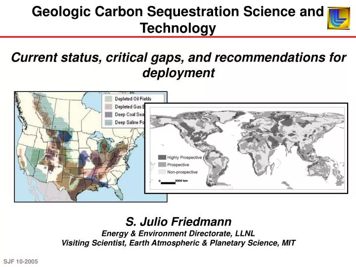
Geologic Carbon Sequestration Science and Technology. Current status, critical gaps, and recommendations for deployment. S. Julio Friedmann Energy & Environment Directorate, LLNL Visiting Scientist, Earth Atmospheric & Planetary Science, MIT.

E N D
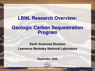
Geologic Carbon Sequestration Science and Technology Current status, critical gaps, and recommendations for deployment S. Julio Friedmann Energy & Environment Directorate, LLNL Visiting Scientist, Earth Atmospheric & Planetary Science, MIT
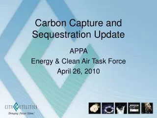
CO2 Capture & Storage (CCS) represents an attractive pathway to substantial GHG reductions • A key portfolio component (with efficiency, conservation, renewables) • Cost competitive to other carbon-free options (e.g., wind, nuclear) • Uses existing technology Pacala & Socolow, 2004 CCS appears at once an ACTIONABLE, SCALEABLE, RELATIVELY CHEAP, BRIDGING TECHNOLOGY
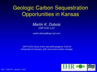
Cumulative Worldwide Gasification Capacity High purity (>90%) CO2 streams are required for storage Refineries, fertilizer & ethanol plants, polygeneration, cement plants, and gas processing facilities are cheapest. These represent significant CO2 volumes and major opportunities to initiate large-scale projects. Currently, mostly natural sources (e.g., CO2 domes) Capture devices on standard existing plants (e.g., PC) are relatively high in cost. Typical PC plant $40-60/t CO2 Typical gasified plant $30-40/t CO2 Oxyfired combustion $30-40/t CO2* Low-cost opportunities $ 5-10/t CO2 IGCC and high-pressure gasification streams appear promising candidates for cost reduction through technology development * Not yet ready for prime time
CO2 can be stored in several geological targets, usually as a supercritical phase • Saline Aquifers • Depleted Oil & Gas fields • (w/ or w/o EOR and EGR) • Unmineable Coal Seams • (w/ or w/o ECBM) • Other options • (e.g., oil shales, basalts) • The storage mechanisms vary by reservoir type Benson, Cook et al., in press IPCC Report on Carbon Sequestration There is enough knowledge and technology to execute today at large scale successfully with high confidence
There are ongoing issues that prompt concern in carbon sequestration science & technology • Subsurface issues: • Is there enough capacity to store CO2 broadly? • Do we understand storage mechanisms well enough? • Could we certify and decertify injection sites with our current level of understanding? • Once injected, can we monitor and verify the subsurface CO2? • Near surface issues: • How might capacity distribution affect deployment and siting of zero-emission projects and new coal plants ? • What are the probabilities of CO2 escaping from injection sites?What are the attendant risks? Can we detect leakage if it occurs? • Will surface leakage negate or reduce the benefits of CCS? What are the key science and technology gaps that could limit or prevent deployment of CCS, and how can we bridge those gaps?
Conclusions To a first order, the science supports successful carbon storage. Science and technology gaps appear resolvable and should focus on key problems (e.g., wells) LARGE SCALE tests are crucial to understanding successful deployment of carbon capture and sequestration (CCS) and creating appropriate policy/economic structures. No test planned to date is sufficient with respect to scale, duration, monitoring, and analysis.
A central priority of any decarbonized fossil fuel strategy should be large CCS projects Of order 10 large scale field experiments and demonstration projects worldwide (3-4 in the US) in a suite of geologic settings could largely resolve present scientific uncertainty and demonstrate engineering practice for practical sequestration projects Each project: 8-10 years – $13-28 M/yr
There appears to be enough global storage capacity to sequester 2 Gt C/yr (7 Gt CO2) indefinitely • There appears to be more than enough accessible rock volume for sequestration • Large capacity exists in US, Canada, other OECD countries • Appears viable in most of world, including India and China Site-specific, economic estimates Dooley et al., 2004 Highest value, early sites Total capacity volumes are less useful that injection rate estimates. Ultimately, high-quality easy storage will be used first, with lower grade rock volumes used for sequestration through time. Global, total volume estimates
World : 100 -200,000 GT Europe : 1 – 2449 GT USA : 2 – 3747 GT Canada : 2 – 4000+ GT Australia : 4 – 740 GT Japan : 0 – 80 GT Almost all current capacity estimates are poor – this is a high priority issue Standard assessment methods would suffice to estimate total capacity and local injection rates, but have not been properly assessed outside Australia and Alberta Bradshaw et al., 2004 As a policy action geological capacity surveys of key basins are low in cost but should underlie any nation’s CCS strategy (USGS or equivalent should execute, not DOE)
Projected Costs of CCS Technology Elements 100 10 1 US Dollars/ ton CO2 2 0.1 0.01 0.001 0.0001 Capture Storage MMV Assessment Desire for information identified in end state characterization helps in planning Recognition of need for 2025 large-scale deployment and 250 Gt C abatement highlights urgent need of assessments Questions of cost emerge and can be addressed (e.g., order of $10M) Questions of execution emerge and can be addressed (e.g., CGS vs. ARC) Questions of funding emerge and can be addressed (e.g., industrial vs. federal sponsorship) Friedmann et al., in press
Site selection should require due diligence in characterization & validation Ideally, project site selection and certification would involve detailed characterization. In most cases, this will require new geological and geophysical data sets. Injectivity Capacity Effectiveness • For Depleted Oil & Gas Fields: • Injectivity & capacity well established • Objective measures of effectiveness exist • For Saline Aquifers: • ICE could be estimated; would probably require exploratory wells and 3D seismic • Include cores, followed by lab work • For Unmineable Coals: • Injectivity could be tested • Capacity is poorly understood • Effectiveness is not well understood or demonstrated
Open issues in site selection • For Depleted Oil & Gas Fields: • Incremental cost concerns in most cases • For Saline Aquifers: • Approximation of potential fast-paths to surface • Accurate rendering of reservoir heterogeneity and residual saturation • Understanding of local stress tensor and geomechanics • For Unmineable Coals: • Understand transmissivity between fracture and matrix pore systems. • Understanding sealing architecture near seam • Understand cleat structure and its response to pressure transient The threshold for validation is different for each site and reservoir class. Policy is needed to establish a regulatory framework aimed at appropriate validation of selected sites for certification
Once injection begins, measurement, monitoring, and verification (MMV) is required • MMV serves these key roles: • Understand key features, effects, & processes • Injection management • Delineate and identify leakage risk and leakage • Provide early warnings of failure • Verify storage for accounting and crediting • Currently, there are abundant viable tools and methods; however, only a handful of parameters are key • Direct fluid sampling via monitoring wells (e.g., U-tube) • T, P, pH at all wells (e.g., Bragg fiberoptic grating) • CO2 distribution in space: various proxy measures • (Time-lapse seismic clear best in most cases) • CO2 saturation (ERT, EMIT likely best) • Surface CO2 changes, direct or proxy • (atmospheric eddy towers best direct; LIDAR may surpass) • (perfluorocarbon tracing or noble gas tracing best proxies) • Stress changes (tri-axial tensiometers)
Effective (MMV) for a typical site should focus on near surface & near reservoir in four stages • Assessment and planning • Site characterization • Simulation & forward modeling • Array design and planning • Baseline monitoring • May take days to years • May require reworking wells • Operational monitoring during injection • Array monitoring during and after injection • Surface & subsurface components • May have additional tools along high-risk zones • Recurrence and duration determined by site parameters • Need for formal integration Practical monitoring programs should be (1) crafted around utility, robustness, and automation, (2) based on a sound understanding of local geology and geography, and (3) formally integrated
Open issues in MMV • By what means can we formally integrate and compare the results of orthogonal MMV surveys? • What are likely durations of monitoring after injection stops? • Detection limits: • What are detection thresholds for individual technologies? • What limits detection as a function of subsurface or surface concentration, location, and distribution? • Need to focus on surface detection methods and approaches: • How can one measure flux above background? • How can one configure a surface array to answer key questions • How can one optimize an array given a geography and geology? Coordinated field tests are needed to compare and contrast methods in terms of efficacy. Multiple field tests can serve as the basis for policy and regulation.
Leakage risks remain a primary concern • High CO2 concentrations (>15,000 ppm) can harm environment & human health. • There are other potential risks to groundwater, environment • Concern about the effectiveness & potential impact of widespread CO2 injection • Economic risks flow from uncertainty in subsurface, liability, and regulations • Elements of risk can be prioritized • Understanding high-permeability conduits (wells and faults) • Predicting high-impact effects (asphyxiation, water poisoning) • Characterizing improbable, high-impact events (potential catastrophic cases)
Well-bore integrity remains the predominant risk issue, with well plugging the main event Investigators, regulators, and modelers need empirical and statistical data sets to condition risk of complete well failure. After Gasda et al., 2004 Princeton Environmental Institute
Plugs remain a key concern, particularly for old wells (orphaned and abandoned) Plug technology has improved over time due to regulation http://www.richardseaman.com/Travel/NewZealand/NorthIsland/Rotorua/MudPools/SunkenMudPool.jpg http://www.hardwarestore.com/media/product/221101 _front200.jpg http://fotos.naturspot.de/bilder/11-336.html • 1930’s – 1953 • Mud • Cement with no • additives • 1953 – present • Standard Portland • Cement • Cement with additives • 1850’s – 1920’s • Animal Carcasses • Mud • Debris • Nothing There is no census for the number of leaking orphaned wells or knowledge of overall long-term well isolation performance for CO2
Outline of large-scale demonstration and experimental projects using low-cost CO2 Basic requirements for a successful large-scale project include both the logistical and scientific aspects, for ~8 years Detailed pre-drill assessment $2-4 M Injection (1-2) & monitoring wells (3-8) $3-8 M CO2(500,000 – 1,000,000 t/y) $1.5-10 M/y Compression $3-6 M/y Monitoring (multiple methods) $2.2-6.4 M/y Analysis and modeling $5-7 M/y Post-injection sampling/recompletion $3-8 M Total $107-225M Annual $13 – 28 M Of the current large-scale projects, only one (Weyburn) approaches these criteria; three pending efforts may come closer, if properly funded and coordinated Small-scale projects cannot deliver the science and technology because of intrinsic questions of scale (e.g., pressure transient and reservoir heterogeneity effects)
WY: Lost Cabin (1Mt) or La Barge (4Mt) • Abundant EOR and saline aquifers • Cheap drilling, good geological infrastructure • IL: Fertilizer plants • >250Kt each • Similar to Appalachians • Important play • WV: Indian Creek field • 65% CO2 • Mt Simons & Oriskany • Ohio River Valley adj. • TX/LA: Gulf Refineries • 0.5 – 4 Mt each (100-500 MW power plant eq.) • Largest capacity in US • Best geological infrastructure Within the US, the 3-4 sites are fairly easy to plan using anthropogenic sources The choice is based on representative nature of reservoirs
The DOE is the likely institution to execute an R&D program; others are needed Given the current gaps, the DOE will likely play the greatest role and require the highest funding levels, but cannot undertake all critical roles well. • DOE • Basic R&D (e.g., geomechanics; simulations) • Large-scale demonstrations & field experiments • MMV applications and technology development • Applied science (e.g., risk assessment) • DOI (USGS) • Define formal US methodology for capacity assessment • Conduct and render capacity estimates • EPA • Determine sound science-based regulations • Construct protocols for site selection, certification, and decertification This division of labor is likely to create institutional conflicts that may be resolved through clear executive or congressional delineation of roles and adequate funding
Wisconsin has limited but real options for geological carbon storage The mid-continent rift appears to have deep, permeable units suitable for storage • Bayfield group promising: up to 18% porosity possible. • Initial work is just literature and surface geology work, limited aeromagnetic surveys • Next step: 3D seismic volume over most promising area • Next step: exploratory borehole • Next-step: EIS and additional site characterization data In addition, pipelines to Michigan or Illinois basins are reasonable options given market costs.
Underground coal gasification may provide an additional lever to lower IGCC & capture costs Gasification occurs in situ. The technology has been well tested and used >40 years • Combination of injection & production wells • Ignition causes partial combustion; heat causes gasification • Air injection makes conventional syngas – suitable for IGCC • O2 injection makes rich syngas w/o N2; suitable for synthetic natural gas, liquid fuels, H2 Courtesy ErgoExergy This technology is moving forwards today! It should be carefully studied, and CCS encouraged.
UCG has substantial economic and environmental benefits Wabash, IN • No mining • No purchase of coal; no ash management • No gasifier purchase or operation • High pressure syngas stream = low-cost CO2 separation • No particulates or NOx; sulfur management straightforward • Good coincidence between CCS and UCG sites Chinchilla, AUS These aspects have increased interest in developing countries (India, China) with high sulfur & high ash coals. Courtesy ErgoExergy
UCG should always proceed in a way to manage and reduce groundwater risks UCG can contaminate groundwater if executed poorly! Site selection and operation are both important • No mining; no ash management • No gasifier purchase or operation • High pressure syngas stream = low-cost partial decarbonization • No particulates or NOx; sulfur management straightforward • Good coincidence between CCS and UCG sites Courtesy ErgoExergy This technology is moving forwards today! It should be carefully studied, and CCS encouraged.
Sites of note Pending UCG reduces the cost of CO2 management! The high pressure of UCG syngas can serve to reduce the cost of carbon capture and separation substantially • Good coincidence between UCG and CCS sites • Liquid, natural gas, and H2 applications require CO2 separation • UCG geological characterization can serve CCS site planning This technology is moving forwards today! It should be carefully studied, and CCS encouraged.
For the US and other nations, the likely benefits of aggressively adopting these measures is large • Substantial reduction of GHG emissions from fossil energy plants in the US • Ready technology to reduce GHG emissions in key developing nations • Continued long-term use of coal & gas electric power • Potential to partly decarbonize polygeneration streams • Additional recovery of hydrocarbons from existing field • Ability to act early US leadership would help national and international industry plan better for a carbon constrained world, and will signal commitment to important OECD and developing nations
Conclusions To a first order, the science supports successful carbon storage. Science and technology gaps appear resolvable and should focus on key problems (e.g., wells) LARGE SCALE tests are crucial to understanding successful deployment of carbon capture and sequestration (CCS) and creating appropriate policy/economic structures. No test planned to date is sufficient with respect to scale, duration, monitoring, and analysis.
CO2 Capture Costs Today CCS is competitive in cost compared with other technologies Solar PV 100 Late change coal Wind Reforestation Hydro IGCC w/ CO2 capture Biofuels Cost for CO2 avoidance ($/ton CO2) 50 Oil to gas Coal to coal Natural Gas CC w/ CO2 capture Pulverized coal w/ CO2 capture Coal to gas 0 0 20 40 60 80 100 CO2 capture w/ EOR/ECMB Potential CO2 abatement (%) Adapted from Lars Stromberg, Vattenfall AB, Electricity Generation, Sweden, 2001; SPA Pacific
1.0 MgCO3 0.2 NaAlCO3(OH)2 Storage mechanisms are sufficiently well understood to be confident of effectiveness • Physical trapping • Impermeable cap rock • Either geometric or hydrodynamic stability • Residual phase trapping • Capillary forces immobilized fluids • Sensitive to pore geometry (<25% pore vol.) • Solution/Mineral Trapping • Slow kinetics • High permanence • Gas adsorption • For organic minerals only (coals, oil shales)