Download

1 / 12
120 likes | 265 Views
Super Nova/Acceleration Probe. SNAP Electrical Design Estimates. November 16 , 2001 C. Paul Earle. SNAP Functional Block Diagram. Thermal Control & Monitoring. Bright Object Detector. Shutter Control. FPA. S/C C&DH. FPE. ICE. 1553 I/F. Scene. Readout Control Logic.

E N D
Super Nova/Acceleration Probe SNAPElectrical Design Estimates November 16, 2001 C. Paul Earle Electrical
SNAP Functional Block Diagram Thermal Control & Monitoring Bright Object Detector Shutter Control FPA S/C C&DH FPE ICE 1553 I/F Scene Readout Control Logic Instrument Control Electronics Science Data I/F Mass Storage (S/C) Data Buffering A/D CDS Detectors Filters Shutter Door Spectrograph DC-DC Converter A/D Focus Control S/C Power Door open / close Figure 1. Electrical
Science Data Rate FPA Size: 144 CCDs @ 1.6Kx1.6K each ~ 368.6 Mpix 44 HgCdTe @ 2Kx2K each ~ 176 Mpix Spectrograph: 1Kx1K ~ 1Mpix Average Data Rate: ==> 545 Mpix for each 200Sec exposure ==> Data rate (avg) ~ (545Mpix/220Sec) ~ 2.5Mpix/s ~ 40 Mbps @16-bits/pix ~ 20 Mbps (with 2:1 loss-less compression) 220Sec 200Sec integration 20Ssec readout Electrical
Focal Plane Electronics CCD Readout ASIC (3” x 3”) each • 4 A/Ds • 4 CDS chips (Correlated Double Sampling) • Bias & Power Generation • Sequencer & Clock Drivers • 188 Readout ASICs • ~ 10 boards (12” x 12”) • 18 ASICs each, 9 ASICs per side • 2 boxes ~ (13.5”x13.5”x6”) each ~ 9lbs each • Total Power: 156Watt (peak), 22 Watt (avg.) Electrical
Thermal Control Requirements: - 70 zones, controlled within +0.5 deg. C of set point - 1 Heater and 1 Temperature Sensor per zone - Each CCD controlled within +0.1 deg. C of set point - Unregulated Heater Power (120Watts) V+ V+ V+ Heater Sensor (AD590) i (T) (1 of 258) Current TLM Figure 2. Electrical
CCD Temperatures Housekeeping Data (1 of 11) A/D Conv. AD 1672 H/K FIFO Mux 16-ch AD506 V- To Memory + CCD temps (188) - V- Zone Temperatures & Other Telemetry points (1 of 5) Mux 16-ch AD506 A/D Conv. AD 1672 H/K FIFO Power Temp ... . . . To Memory Figure 3. Electrical
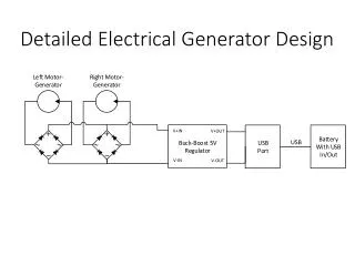
Readout Data Buffering (1 of 188) (1 of 188) Digital MUX (4:1) FIFO Buffer CCD I/F 4 1 To Storage FPE I/F Capture& Control Logic FPGA (1 of 1) Processor Card I/F Figure 4. Electrical
- - + + On/Off Cmd Driver Amp From PLD Controller Door Actuator HK Mux Actuator Current Temp Sensor Actuator Voltage + To Central HK - I+ Sensor Amp Mechanism Control (Door Control Electronics) Figure 6. Electrical
Processor & Memory Board Startup ROM xfmr xcvr 1553 I/F CPU UTMC 69R000 xfmr xcvr xfmr 1553 I/F xfmr RAM (Data Processing) EEPROM Memory (Data Processing) Ethernet I/F S/W Dev. Figure 5. Electrical
I+ I+ Power Distribution DC/DC Converters +15 V +28 VDC +5 V Current Sense + - Voltage Sense + - Figure 7. Electrical
Board Estimates 10 in Mech Control (6W) Data Buffer (3W) Thermal Control (4W) Housekeeping (16W) Data Buffer (3W) Thermal Control (4W) Processor (4W) Data Buffer (3W) Thermal Control (4W) 9 in FPE Power (9.4W) Main Power (20W) Figure 8. Electrical
Main Electronics Box Summary 10 in Estimated Mass ~ 44 lbs Estimated Power ~ 76 Watts (avg.) Estimated Size ~ (19 x 11 x 10) in. 11 in 19 in Figure 9. Electrical