Download
1 / 15
160 likes | 306 Views
Sea Water Scrubber. INTRODUCTION. Crystallox has developed a new generation of horizontal and vertical scrubbers for marine and land based applications.

E N D
INTRODUCTION Crystallox has developed a new generation of horizontal and vertical scrubbers for marine and land based applications. The description and operation of the scrubber is outlined in the technical section of this document. A Crystallox sea water scrubbing system will enable the continued use of high sulphur residual fuel and at the same time remain fully compliant with current legislation up to and beyond 2020.
Legislation International legislation around marine fuel is covered under IMO – the International Maritime Agency. The revision of IMO MARPOL Annex VI has now formally been adopted, and MARPOL Annex VI Regulation 14 allows ships to fit sea water scrubbing systems as an alternative to running more costly low sulphur marine and distillate fuels. In addition to the newly-designated IMO marine fuel legislation, ships fuel is also governed by European Union Directive EC2005/33. This legislation also allows for the use of sea water scrubbing systems as an alternative means of compliance. The design of this scrubber technology means that a Crystallox systems is fully compliant with the requirements of both IMO MARPOL Annex VI, Regulation 14 and Directive EC2005/33
Performance The Crystallox scrubbing system will achieve the legislated emissions of SO2 (better than 0.1% fuelrequirement) and based on current installation data, will significantly reduce Particulate Matter (PM) emissions.
Approval Crystallox sea water scrubbing complies with the IMO Sea Water Scrubbing Guidelines utilizing Method B for approval (in-service compliance by continuous monitoring). Method B provides for continuous exhaust gas monitoring on all the scrubbed exhausts in addition to monitoring the system wash water overboard discharge.
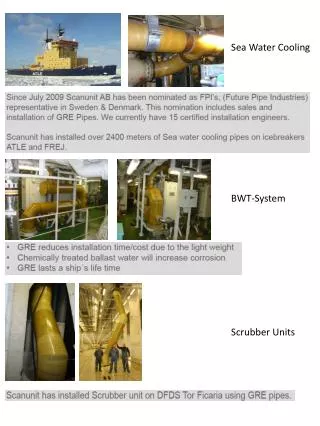
Equipment Description The scrubber design allows for the installation of the equipment inside the proposed funnel spacing. This minimizes installation time on the ship, and allows the scrubber to be installed using a crane. Included in the supply is the following: Scrubber vessel The scrubber design information is as follows: • Inlet section to the scrubber in acid resistant high temperature alloy • Main scrubber body in acid resistant FRP lined Carbon Steel • Scrubber dimensions would be adjusted to suit a horizontal layout. One typical section would be 1,200mm diameter by 6m long. • Weight empty is 5 tonnes. Weight operational is 8 tonnes. • Alloy demister located at the exit of the scrubber. • Injector wash water nozzles in 316L SS • Internal piping in acid resistant GRE • Induced draft fan located at the scrubber outlet.
Water Treatment Plant. The water treatment plant is a pressurised separator which is designed to skim off the majority of the PM that is entrained in the wash water. The Separator Tank will require to be installed at a lower deck, and the installation is excluded in the price. Design features are as follows: • Inlet and outlet connections at 400mm • Constructed in acid resistant GRE or FRP lined Carbon Steel • Dimensions are 2.0m diameter by 4m tall. • Includes level control instrumentation and air vent control • Outlet connection 25mm in diameter to collection tank. Included in the supply is a collection tank for the PM removed from the separator tank. The liquid/PM mixture is skimmed off from the separator tank once a day, and the PM allowed to settle in the collection tank. The clear liquid that settles above the heavier PM lying in the bottom of the collection tank is pumped back into the inlet to the separator tank. The adsorbed SO2 remains in solution and passes out to the sea as sodium sulphate after mixing with the engine cooling water. Monitoring Instrumentation and Controls Included in the price is instrumentation and controls to ensure that the scrubber complies with IMO Sea Water Scrubbing Guidelines, Method B. This includes meters for SO2 and CO2 in the stack, and PAH, pH and Turbidity in the inlet and outlet wash water lines. The control panel, including the safety shutdown system, would normally be installed in the main control room. Wiring to and from all electrical items, including the supply pumps, is excluded in the price. Supply Pumps The seawater pumps to fully operate a scrubber system are principally in three groups;
Water Pumps • Wash water supply pumps (standard sea water pumps) providing the scrubbing medium to the scrubber. • Impellor in NiAl-bronze, or equal, with stainless steel shaft • Casing in Bronze RG10, or equal • Motor 150kW, IP55, 440/3/60, Class F/F. • Each pump plus motor estimated at 2,000kg. • There would be 2 supply pumps, one operational and an installed spare. The pumps are designed to supply 500m3/hr wash water at a pressure of 7bar.g. • Return pumps are not required in this case as there is sufficient height differential available between the scrubber and maximum loaded draft to produce required differential pressure across the separator vessel. • Reaction water pumps are not required as it is assumed that sufficient reaction water will be provided by existing ships cooling system to provide necessary neutralization of wash water pH before overboard discharge.
Eduction Inserts Inserts are supplied which will require fitting into the 2 main engine exhaust stacks. The inserts are designed such that they will have no effect on back pressure on the engines or boiler, whether the scrubber is operational or not. The nozzles are built in carbon steel, and generate a localised vacuum inside the stack which pulls the exhaust gases into the scrubber. Valves in the exhaust stack are not required with this system. Installation of the nozzles is excluded in the price. Also excluded in the price is the ducting from the stacks to the scrubber inlet. Induced Draft Fan The fan is designed to pull the exhaust gases from the stacks and into and through the scrubber all the way to the stack exit. Design features for the fan are as follows: Designed to handle the flow rates from the engines and boilers combined and as specified. Impellor in Super Duplex or equal Casing in carbon steel lined with acid resistant membrane Direct coupled motor adsorbing 60kW
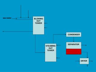
TECHNICAL CASE - system Dry gas <80%RH In stack exhaust gas monitoring for NO NO2 CO2 & SO2…… SWS Note: 45t/hr is based on 100% scrubbing a 3.5% sulphur fuel. Water flow would be less for lower % 1 MW Exhaust Engine Room Discharge water monitor pH 6.5 Oil <0.5ppm HC CCS 45t/hr per MW 5% to 10% additional oily waste
Thank you for your attendanceXastra TechnologiesGreece , Norway ,UK ,Cyprus ,UAE