Download
1 / 15
210 likes | 462 Views
Connectors and Cables. Types of connectors and cables Wiring standards Soldering principles Cable testing. Connectors Microphones. Professional quality will always use either XLR or RTS XLR is the most common Locking connector for greater reliability. 3 pin XLR. Connectors Microphones.

E N D
Connectors and Cables Types of connectors and cables Wiring standards Soldering principles Cable testing
Connectors Microphones • Professional quality will always use either XLR or RTS • XLR is the most common • Locking connector for greater reliability 3 pin XLR
Connectors Microphones • Pin out • Term which defines which conductors land on which pins • There are standards for different devices • The standards change in different parts of the world Pin 1 – Ground Pin 2 – Signal Hot Pin 3 – Signal Return
Connectors • Ring – Tip – Sleeve • Used for balanced mic signals • More often used unbalanced for multiple channel connections Balanced Pin 1 – Shield Pin 2 – Signal Hot (+) Pin 3 – Signal Return (-) Unbalanced Pin 1 – Signal Return (-) Pin 2 – Signal 1 Hot (+) Pin 3 – Signal 2 Hot (+)
Connectors • RCA plugs • Sometimes called phono plug • Not to be confused with ¼” phone plugs • Always unbalanced Pin 1 – Signal Hot (+) Pin 2 – Signal Return (-)
Balanced vs. Unbalanced • Unbalanced – 2 conductors. Hot and return • Often the return is a screen or braid around an inner conductor • Low levels of noise resistance • Good for short cable runs at line level or speaker level • Balanced – 3 conductors. Hot, return and shield • Shield is a braid or metallic foil around two inner conductors • Sometimes inner conductors are a “twisted pair” • Shield is connected to ground and bleeds off any induced current • High levels of noise resistance • Good for long cable runs. Typically at microphone level.
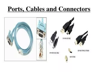
Cables • Wire • One individual conductor • Cable • Two or more conductors combined together in a flexible jacket
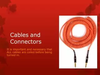
Cables • Cables in theatrical applications receive very rough treatment • Stepped on, genie lifts and forklifts roll over, twisting and pulling… • Even the best audio equipment in the world will not work with damaged cables! • Coiling • The over the forearm method is about the worst thing you can do to any cable • The wires inside the cable have a natural “lay”. • They will coil nicely if they are allowed to • Forcing the wires to bend will weaken and eventually break the wire causing shorts or intermittent connections.
Cables • Cables should always be run “cleanly” • Use the shortest lengths you can. • Avoid large coils when possible • This allows for an easy concentration of induced noise • Never bend cables over sharp edges or right angles • Dropping a cable over and I-beam for example • Always tie up or tape down under carpets or mats or use industrial cable covers. • Avoid using “gaff tape” directly on cable jackets. • Tape will often leave behind a residue of stickiness • If two adhesive sides come together it is very difficult to remove.
Cables • Snakes • A cable with multiple pairs of conductors, each with it’s own screen protected by an overall insulating jacket “Tails” “Break out” box
Cables • Loudspeaker cable • Carries much higher electrical power than mic or line level cables • Need to be much larger gauge with heavy duty connectors on each end or bare wires • Wire has it’s own internal resistance which will degrade the signal before it reaches the speaker • 12 gauge 0.159 Ω / 100 feet • 16 gauge 0.402 Ω / 100 feet • 24 gauge 2.567 Ω / 100 feet
Cable Testing • Tools of the trade • Multi-meter • Device which can measure • AC & DC voltage • Remember AC voltage changes with time • Most meters take and average, NOT RMS value • RMS = root-mean-square, which is a more accurate means of measuring voltage • AC & DC current • Resistance • Continuity • Some meters will measure other things as well • Battery checker • Diode checker
Cable Testing • Oscilloscope • A device which draws a graph of a changing electrical signal in real-time • Allows you to view exactly what the sine wave looks like • Usually a large bench test piece of equipment not usually used in simple sound equipment testing • Line tracer • “Fox and Hound” • The “fox” puts an AC signal on a wire and the “hound” picks it up at the other end • The “hound” looks for the changing magnetic field that the “fox” produces • Can be measured through insulation
Soldering • Here's a summary of how to make the perfect solder joint. • All parts must be clean and free from dirt and grease. • Try to secure the work firmly. • "Tin" the iron tip with a small amount of solder. Do this immediately, with new tips being used for the first time. • Clean the tip of the hot soldering iron on a damp sponge. • Many people then add a tiny amount of fresh solder to the cleansed tip. • Heat all parts of the joint with the iron for under a second or so. • Continue heating, then apply sufficient solder only, to form an adequate joint. • Remove and return the iron safely to its stand. • It only takes two or three seconds at most, to solder the average joint. • Do not move parts until the solder has cooled. • Troubleshooting Guide • Solder won't "take" - grease or dirt present – de-solder and clean up the parts. • Joint is crystalline or grainy-looking - has been moved before being allowed to cool, or joint was not heated adequately - too small an iron/ too large a joint. • Solder joint forms a "spike" - probably overheated, burning away the flux.
For Next Class • Read • Mixing Desks, Kai’s Sound Handbook • P. 66-82, Leonard • Within this reading section, there is some out of date discussion of specific makes and models of equipment. This specific material will NOT be on any test.