Download
1 / 27
270 likes | 403 Views
Implementing the Controller. Outline. Implementing the Controller With JK Flip-flops Decoder + D flip-flops One Flip-flop per State Multiplexers PLA/ROM. Outline. Implementing the Controller With JK Flip-flops Decoder + D flip-flops One Flip-flop per State Multiplexers PLA/ROM.

E N D
Outline • Implementing the Controller • With JK Flip-flops • Decoder + D flip-flops • One Flip-flop per State • Multiplexers • PLA/ROM
Outline • Implementing the Controller • With JK Flip-flops • Decoder + D flip-flops • One Flip-flop per State • Multiplexers • PLA/ROM
Implementing the Controller • Once the state table is obtained, the controller can be implemented using one of these techniques. 1. Traditional method: With JK flip-flops • design done at gate level. • suitable for small controllers. • procedure: prepare state table, use K-maps to obtain next-state/output functions. 2. Decoder + D flip-flops • suitable for moderately large controllers. • procedure: use decoder to obtain individual states; from the state table, obtain the next-state functions by inspection.
Implementing the Controller 3. Multiplexers • a more structured approach to implement controller. • suitable for moderately large controllers. • three level structure: • first level consists of multiplexers that determine the next state of the register; • second level is a register that holds the present state; • third level has a decoder to provide separate output for each controller state.
Implementing the Controller 4. One flip-flop per state • also known as One-Hot Spot Method of ASM synthesis. • procedure: allocate one flip-flop per state; from state table, determine the formulae to set each flip-flop; must ensure that controller is properly initialized. 5. PLA/ROM • highly regular approach. • ROM approach uses a very simple table lookup technique but suffers from large number of don’t care states. • PLA can handle don’t care states well but design method is still at gate-level.
Outline • Implementing the Controller • With JK Flip-flops • Decoder + D flip-flops • One Flip-flop per State • Multiplexers • PLA/ROM
Implementing Controller: With JK Flip-flops • State table obtained from ASM chart: • Corresponding state table using JK flip-flops:
Outline • Implementing the Controller • With JK Flip-flops • Decoder + D flip-flops • One Flip-flop per State • Multiplexers • PLA/ROM
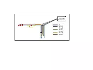
G1 ? D Q T0 2x4 decoder T1 G0 D ? unused Q T2 clock Implementing Controller: Decoder + D Flip-flops • The flip-flop input functions can be obtained directly from the state table by inspection. • This is because for the D flip-flops, the next state = flip-flop D input. • Decoder is then used to provide signals to represent different states.
Implementing Controller: Decoder + D Flip-flops • Given the state table: • We can directly determine the inputs of the D flip-flops for G1 and G0. DG1 = T1.A2.A3 DG0 = T0.S + T1
A2 G1 D Q A3 T0 2x4 decoder T1 G0 D unused Q S T2 clock Implementing Controller: Decoder + D Flip-flops • Flip-flop input functions: DG1 = T1.A2.A3 DG0 = T0.S + T1 • Circuit:
Outline • Implementing the Controller • With JK Flip-flops • Decoder + D flip-flops • One Flip-flop per State • Multiplexers • PLA/ROM
? T0 ? T1 D Q : : D Q clock Implementing Controller: One Flip-flop per State • Require n flip-flops for n states; each flip-flop represents one state. (Other methods: n flip-flops for up to 2n states.)
Implementing Controller: One Flip-flop per State • Formulae for next state can be obtained directly from state table: • If there is only one line going into the state, then formula = input condition ANDed with the previous state. • If there are more than one line, then formula = Ored of all the conditions found in (1).
S=0 A2=0 S=1 T0 T1 A2=1, A3=0 A2=1, A3=1 T2 Implementing Controller: One Flip-flop per State • State diagram: • State table: • Flip-flop input functions: DT0 = T2 + S'.T0 DT1 = S.T0 + A2'.T1 + A2.A3'.T1 = S.T0 + (A2.A3)'.T1 DT2 = A2.A3.T1
preset T0 D D D Q Q Q S T1 A2 A3 T2 clock clear Implementing Controller: One Flip-flop per State • Circuit diagram below. To initialize to state T0, set flip-flop of T0 to 1 and clear the rest to zero. DT0 = T2 + S'.T0 DT1 = S.T0 + (A2.A3)'.T1 DT2 = A2.A3.T1
D D D Q Q Q S Q' T0 T1 A2 A3 T2 clock clear Implementing Controller: One Flip-flop per State • Alternative: Use Q' output for T0, and input function for T0 is complemented. To initialize, clear all flip-flops to zero. DT0 = (T2 + S'.T0)' DT1 = S.T0 + (A2.A3)'.T1 DT2 = A2.A3.T1
Outline • Implementing the Controller • With JK Flip-flops • Decoder + D flip-flops • One Flip-flop per State • Multiplexers • PLA/ROM
Implementing Controller: Multiplexers • Purpose of multiplexer is to produce an input to its corresponding flip-flop equals to the value of the next state. • The inputs of multiplexers are determined from the decision boxes and state transitions in the ASM chart.
Implementing Controller: Multiplexers • Example 1: • Given the state table. • Reformat the state table.
Implementing Controller: Multiplexers • Obtain multiplexer inputs:
D D Q Q 0 0 1 2 3 A2 A3 G1 MUX1 0 S1 S0 T0 2x4 decoder T1 S1 S0 S T2 0 1 2 3 G0 1 MUX0 0 clock Determine next state of register Hold present state Implementing Controller: Multiplexers • Draw the circuit:
T0 00 0 w 1 T1 01 0 1 x T3 11 T2 10 0 1 1 0 y y 0 1 1 0 z z Implementing Controller: Multiplexers • Example 2:
0 0 1 2 3 D D Q Q 1 G1 MUX1 y y z' S1 S0 T0 2x4 decoder T1 T2 S1 S0 w T3 0 1 2 3 G0 x' MUX0 y z y' clock Implementing Controller: Multiplexers
Outline • Implementing the Controller • With JK Flip-flops • Decoder + D flip-flops • One Flip-flop per State • Multiplexers • PLA/ROM
Commands to architecture External command PLA/ROM Present state Next state Register to represent states Implementing Controller: PLA/ROM • Similar to the design using D flip-flops and a decoder. • The only difference is PLA essentially replaces the decoder and all the gates in the inputs of the flip-flops.